12
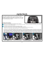
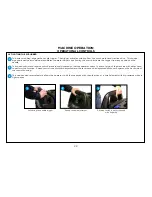
Connect the cleaning pad to the disk pad drivers by centering them on the drivers.
MACHINE PREPARATION
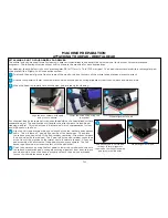
ATTACHING CLEANING PADS TO YOUR PAD DRIVERS - DISK HEAD
Depress position “A” for 1 second
then depress position “B”
1
If using floor pads with your pad drivers:
1
2
3
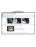
Place your pad drivers on a work surface and remove the center lock fitting from the pad drivers. To do so, squeeze the center lock wires
inward and lift the center lock off the pads.
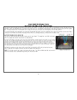
Remove the pad drivers by locating the automatic off switch on the lower control panel at the rear of the machine. Depress position “A”
for 1 second and then depress position “B” to “click-off” the pad drivers.
4
Squeeze center lock wires inward and press center lock down, tab side first, compressing the pad and then release the wires so that they
lock in place holding the pad. Repeat for the other pad driver.
NOTE:
The S-Series pad drivers are tufted pad drivers. Do not use a pad driver on the floor without a pad in place. This will cause damage
to your floor.
Disconnect center lock fitting & lay
next to the pad driver
Center pad on pad driver
Squeeze center lock wires inward,
press down onto pad & release wires
2
3
4
Close up showing center lock tab &
wires
4
wires
tab
Summary of Contents for S Series
Page 45: ...45 FRAME ASSEMBLY WITH URETHANE WHEELS...
Page 46: ...46 FRAME ASSEMBLY WITH FOAM FILLED WHEELS...
Page 48: ...48 ON BOARD CHEMICAL INJECTION ASSEMBLY OPTIONAL...
Page 49: ...49 BATTERY ASSEMBLY...
Page 50: ...50 RECOVERY TANK ASSEMBLY...
Page 51: ...51 SQUEEGEE ASSEMBLY S 24...
Page 52: ...SQUEEGEE ASSEMBLY S 28 52...
Page 53: ...SQUEEGEE ASSEMBLY S 32 53...
Page 54: ...54 SQUEEGEE LINKAGE ASSEMBLY...
Page 55: ...55 HEAD LIFT ASSEMBLY...
Page 56: ...56 HEAD ASSEMBLY DRAWING 1 OF 2 S 24...
Page 57: ...57 HEAD ASSEMBLY DRAWING 2 OF 2 S 24...
Page 58: ...58 HEAD ASSEMBLY S 28 DISK...
Page 59: ...59 HEAD ASSEMBLY S 32...
Page 60: ...60 HEAD ASSEMBLY LOWER S 28 ORBITAL...
Page 61: ...61 HEAD ASSEMBLY UPPER S 28 ORBITAL...
Page 62: ...62 CONTROLS ASSEMBLY S 24...
Page 63: ...63 CONTROLS ASSEMBLY S 28 S 32 DISK...
Page 64: ...64 CONTROLS ASSEMBLY S 28 ORBITAL...
Page 65: ...65 CONTROLS ASSEMBLY BATTERYSHIELDTM CHEMICAL INJECTION SYSTEM OPTIONAL...
Page 66: ...66 ELECTRONICS ASSEMBLY S 24...
Page 67: ...67 ELECTRONICS ASSEMBLY S 28 S 32 DISK...
Page 68: ...68 ELECTRONICS ASSEMBLY S 28 ORBITAL...
Page 69: ...69 ELECTRONICS ASSEMBLY BATTERYSHIELDTM...
Page 70: ...70 CHARGER ASSEMBLY ON BOARD...
Page 71: ...WIRING DIAGRAM S 24...
Page 72: ...WIRING DIAGRAM S 28 S 32 DISK...
Page 73: ...WIRING DIAGRAM S 28 ORBITAL...
Page 74: ...WIRING DIAGRAM BATTERYSHIELD OPTIONAL 74...
Page 75: ...WIRING DIAGRAM ON BOARD CHEMICAL INJECTION SYSTEM OPTIONAL 75...

