MACHINE PREPARATION
UNPACKING & BATTERY INSTALLATION
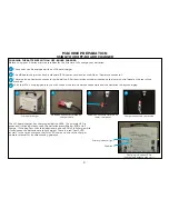
UNPACKING THE MACHINE
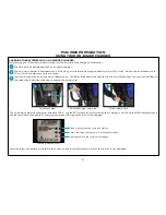
1. Remove the outer packaging.
2. The machine is fastened to the pallet with tie down brackets. Remove the brackets with a 3/8-inch
socket head tip in a cordless screwdriver.
3. The machine is also held in place with four cleats. Remove the cleats with a phillips tip
in a cordless screwdriver.
4. Raise the scrub head of scrubber and put it in the transport position.
5. Using a ramp, push the machine backwards down from the pallet.
5. Keep the pallet and brackets for any future transport needs.
4
BATTERY TYPE
To power the machine you can use either wet batteries or AGM batteries. Other types must not be used.
The maximum dimensions and the weight are:
Width:
7 1/8 in (181 mm)
Length:
10 3/8 in (264 mm)
Height:
11 5/8 in (295 mm)
Weight:
72 lb (33 kg)
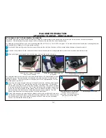
BATTERY INSTALLATION
The machine will be supplied with a battery charger and either four 6V wet or AGM
batteries. The batteries must be housed in the battery compartment beneath the
recovery tank.
To insert batteries:
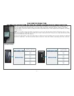
1. Lift the recovery water tank, opening it as far as it will go using the side handle.
2. The batteries must be lowered into the compartment using lifting and
transportation means suitable for the weight and dimensions.
3. They must be connected together in series, to obtain overall voltage of 24V on
the lugs.
NOTE: Fully charge the batteries before using the machine.
NOTE:
Your charger must be set according to the type of battery you install. Read charging section of manual for further instructions on how
to set your charger correctly for your battery type.
Battery Connection
Diagram
Tie down bracket
NOTE:
The on-board charger has been programmed to work with the batteries that Pacific Floorcare provides. Using other battery
types not specified for the S-Series mid-size scrubber by Pacific Floorcare may impair performance of the unit and will affect
the life of the batteries.
Recovery tank shown in fully
open position
Cleats
Summary of Contents for S Series
Page 45: ...45 FRAME ASSEMBLY WITH URETHANE WHEELS...
Page 46: ...46 FRAME ASSEMBLY WITH FOAM FILLED WHEELS...
Page 48: ...48 ON BOARD CHEMICAL INJECTION ASSEMBLY OPTIONAL...
Page 49: ...49 BATTERY ASSEMBLY...
Page 50: ...50 RECOVERY TANK ASSEMBLY...
Page 51: ...51 SQUEEGEE ASSEMBLY S 24...
Page 52: ...SQUEEGEE ASSEMBLY S 28 52...
Page 53: ...SQUEEGEE ASSEMBLY S 32 53...
Page 54: ...54 SQUEEGEE LINKAGE ASSEMBLY...
Page 55: ...55 HEAD LIFT ASSEMBLY...
Page 56: ...56 HEAD ASSEMBLY DRAWING 1 OF 2 S 24...
Page 57: ...57 HEAD ASSEMBLY DRAWING 2 OF 2 S 24...
Page 58: ...58 HEAD ASSEMBLY S 28 DISK...
Page 59: ...59 HEAD ASSEMBLY S 32...
Page 60: ...60 HEAD ASSEMBLY LOWER S 28 ORBITAL...
Page 61: ...61 HEAD ASSEMBLY UPPER S 28 ORBITAL...
Page 62: ...62 CONTROLS ASSEMBLY S 24...
Page 63: ...63 CONTROLS ASSEMBLY S 28 S 32 DISK...
Page 64: ...64 CONTROLS ASSEMBLY S 28 ORBITAL...
Page 65: ...65 CONTROLS ASSEMBLY BATTERYSHIELDTM CHEMICAL INJECTION SYSTEM OPTIONAL...
Page 66: ...66 ELECTRONICS ASSEMBLY S 24...
Page 67: ...67 ELECTRONICS ASSEMBLY S 28 S 32 DISK...
Page 68: ...68 ELECTRONICS ASSEMBLY S 28 ORBITAL...
Page 69: ...69 ELECTRONICS ASSEMBLY BATTERYSHIELDTM...
Page 70: ...70 CHARGER ASSEMBLY ON BOARD...
Page 71: ...WIRING DIAGRAM S 24...
Page 72: ...WIRING DIAGRAM S 28 S 32 DISK...
Page 73: ...WIRING DIAGRAM S 28 ORBITAL...
Page 74: ...WIRING DIAGRAM BATTERYSHIELD OPTIONAL 74...
Page 75: ...WIRING DIAGRAM ON BOARD CHEMICAL INJECTION SYSTEM OPTIONAL 75...

