17
MACHINE OPERATION
OPERATIONAL CONTROLS
The machine operation and controls were designed to minimize operator training and decrease the need for adjustments during
operation. Additionally, once in operation, Pacific Floorcare’s goal was to provide an ergonomic, easy to use system. Due to this focus, the
S-Series mid-size scrubber’s key operational controls are all within reach so that the operator doesn’t have to remove their hands to perform
the operation - a key to safe, trouble-free, highly productive cleaning.
TURNING THE UNIT ON/OFF
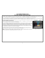
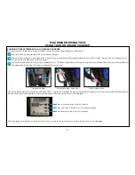
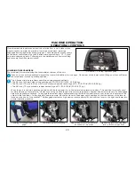
The machine is powered on through a key switch on the upper control panel. Turn the key to the ON
position. You will see the battery meter on the left side of the upper control panel light up to show the
battery charge level.
The key switch is a proven way to eliminate unwanted operation. Simply remove the key and safely store it
away when you have completed scrubbing.
S-Series key switch
SETTING DESIRED SOLUTION FLOW RATE
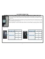
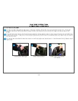
For units that aren’t equipped with a chemical injection system, the next step is to set the unit to the
desired solution flow. This control feature is located at the lower rear of the machine and can be adjusted
from low to high flow spanning a range of 0 to .55 gallons (0 to 2.1 L) per minute.
Solution flow adjustment knob
Summary of Contents for S Series
Page 45: ...45 FRAME ASSEMBLY WITH URETHANE WHEELS...
Page 46: ...46 FRAME ASSEMBLY WITH FOAM FILLED WHEELS...
Page 48: ...48 ON BOARD CHEMICAL INJECTION ASSEMBLY OPTIONAL...
Page 49: ...49 BATTERY ASSEMBLY...
Page 50: ...50 RECOVERY TANK ASSEMBLY...
Page 51: ...51 SQUEEGEE ASSEMBLY S 24...
Page 52: ...SQUEEGEE ASSEMBLY S 28 52...
Page 53: ...SQUEEGEE ASSEMBLY S 32 53...
Page 54: ...54 SQUEEGEE LINKAGE ASSEMBLY...
Page 55: ...55 HEAD LIFT ASSEMBLY...
Page 56: ...56 HEAD ASSEMBLY DRAWING 1 OF 2 S 24...
Page 57: ...57 HEAD ASSEMBLY DRAWING 2 OF 2 S 24...
Page 58: ...58 HEAD ASSEMBLY S 28 DISK...
Page 59: ...59 HEAD ASSEMBLY S 32...
Page 60: ...60 HEAD ASSEMBLY LOWER S 28 ORBITAL...
Page 61: ...61 HEAD ASSEMBLY UPPER S 28 ORBITAL...
Page 62: ...62 CONTROLS ASSEMBLY S 24...
Page 63: ...63 CONTROLS ASSEMBLY S 28 S 32 DISK...
Page 64: ...64 CONTROLS ASSEMBLY S 28 ORBITAL...
Page 65: ...65 CONTROLS ASSEMBLY BATTERYSHIELDTM CHEMICAL INJECTION SYSTEM OPTIONAL...
Page 66: ...66 ELECTRONICS ASSEMBLY S 24...
Page 67: ...67 ELECTRONICS ASSEMBLY S 28 S 32 DISK...
Page 68: ...68 ELECTRONICS ASSEMBLY S 28 ORBITAL...
Page 69: ...69 ELECTRONICS ASSEMBLY BATTERYSHIELDTM...
Page 70: ...70 CHARGER ASSEMBLY ON BOARD...
Page 71: ...WIRING DIAGRAM S 24...
Page 72: ...WIRING DIAGRAM S 28 S 32 DISK...
Page 73: ...WIRING DIAGRAM S 28 ORBITAL...
Page 74: ...WIRING DIAGRAM BATTERYSHIELD OPTIONAL 74...
Page 75: ...WIRING DIAGRAM ON BOARD CHEMICAL INJECTION SYSTEM OPTIONAL 75...


