15
MACHINE PREPARATION
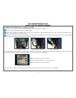
CONNECTING THE SQUEEGEE AND ADJUSTING SQUEEGEE HEIGHT
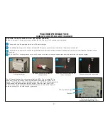
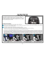
Prior to shipping from the factory, the squeegee assembly is removed from the unit. To connect your squeegee assembly to the machine:
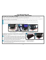
The squeegee blade assembly height is factory set at the optimum water recovery position with the squeegee wheels being
approximately 1/32 inch (1 mm) off the ground allowing the recovery blade to deflect as shown below.
Button screw to raise and lower
squeegee assembly wheels
Align the squeegee assembly retention slots with the easy-grip knobs then tighten until secure.
Attach the recovery hose to the squeegee assembly neck. Make sure to route the hose so that it won’t interfere with the swing of the
squeegee assembly.
Close up of squeegee assembly and
blade deflection
Proper recovery
blade deflection
Slight clearance
off of floor
No clearance
off of floor
1
2
3
4
3
4
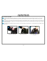
If for some reason your squeegee blade height must be adjusted, it is done so by turning the left button screw located on the squeegee
frame assembly clockwise to raise the left squeegee wheel and counter-clockwise to lower the wheel. The same is true for the right
button screw/squeegee wheel.
After aligning assembly, tighten the
easy-grip knobs and attach the
recovery hose
2
Positioning the squeegee assembly to
mount onto the squeegee frame
1
Easy-grip
knob
Easy-grip
knob
Summary of Contents for S Series
Page 45: ...45 FRAME ASSEMBLY WITH URETHANE WHEELS...
Page 46: ...46 FRAME ASSEMBLY WITH FOAM FILLED WHEELS...
Page 48: ...48 ON BOARD CHEMICAL INJECTION ASSEMBLY OPTIONAL...
Page 49: ...49 BATTERY ASSEMBLY...
Page 50: ...50 RECOVERY TANK ASSEMBLY...
Page 51: ...51 SQUEEGEE ASSEMBLY S 24...
Page 52: ...SQUEEGEE ASSEMBLY S 28 52...
Page 53: ...SQUEEGEE ASSEMBLY S 32 53...
Page 54: ...54 SQUEEGEE LINKAGE ASSEMBLY...
Page 55: ...55 HEAD LIFT ASSEMBLY...
Page 56: ...56 HEAD ASSEMBLY DRAWING 1 OF 2 S 24...
Page 57: ...57 HEAD ASSEMBLY DRAWING 2 OF 2 S 24...
Page 58: ...58 HEAD ASSEMBLY S 28 DISK...
Page 59: ...59 HEAD ASSEMBLY S 32...
Page 60: ...60 HEAD ASSEMBLY LOWER S 28 ORBITAL...
Page 61: ...61 HEAD ASSEMBLY UPPER S 28 ORBITAL...
Page 62: ...62 CONTROLS ASSEMBLY S 24...
Page 63: ...63 CONTROLS ASSEMBLY S 28 S 32 DISK...
Page 64: ...64 CONTROLS ASSEMBLY S 28 ORBITAL...
Page 65: ...65 CONTROLS ASSEMBLY BATTERYSHIELDTM CHEMICAL INJECTION SYSTEM OPTIONAL...
Page 66: ...66 ELECTRONICS ASSEMBLY S 24...
Page 67: ...67 ELECTRONICS ASSEMBLY S 28 S 32 DISK...
Page 68: ...68 ELECTRONICS ASSEMBLY S 28 ORBITAL...
Page 69: ...69 ELECTRONICS ASSEMBLY BATTERYSHIELDTM...
Page 70: ...70 CHARGER ASSEMBLY ON BOARD...
Page 71: ...WIRING DIAGRAM S 24...
Page 72: ...WIRING DIAGRAM S 28 S 32 DISK...
Page 73: ...WIRING DIAGRAM S 28 ORBITAL...
Page 74: ...WIRING DIAGRAM BATTERYSHIELD OPTIONAL 74...
Page 75: ...WIRING DIAGRAM ON BOARD CHEMICAL INJECTION SYSTEM OPTIONAL 75...

