5
MACHINE PREPARATION
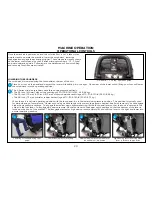
BATTERY POWER LEVEL INDICATORS
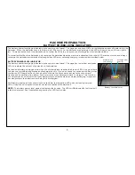
The battery power level gage is located on the upper control panel. The gage has a series of LEDs to indicate the amount of power left in the
batteries. When the batteries have a full charge, all LEDs are lit. As the batteries are discharged, the LEDs will begin to go out from right to
left. To maximize the life of the batteries, do not allow the LEDs to go beyond the discharge level as described below.
To maximize the life of the batteries, only recharge the batteries when the machine is operated for a total of 30 minutes or more and always
recharge the batteries immediately after usage when LEDs are indicating charging is required as described below.
BATTERY POWER LEVEL INDICATOR
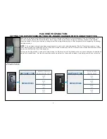
The battery power level gage is located on the upper control panel. The gage has red, yellow and green
LEDs to indicate the amount of power left in the batteries.
On lead acid battery-equipped units, when the discharge level reaches the first red LED, it is a good time
to finish your scrubbing application and recharge the unit. If you do choose to continue scrubbing, when
the last red LED begins to flash, the unit will shut down the brush motor but leave the vacuum and
traction drive operational to perform final water recovery and transport back to storage. This function
not only serves as an indicator that your battery level has reached a point where recharging is required,
but also protects the batteries from being fully discharged.
AGM battery-equipped units should not be used after the last yellow LED goes out leaving only red
LEDs. Using the unit beyond this point can reduce the life of the batteries.
NOTE:
The battery power level gage also displays fault codes. The LEDs will flash specific fault codes if
a fault is detected. See Troubleshooting section for LED fault codes.
Battery Level Indicator
Recharge AGM
batteries
Recharge lead
acid batteries
Summary of Contents for S Series
Page 45: ...45 FRAME ASSEMBLY WITH URETHANE WHEELS...
Page 46: ...46 FRAME ASSEMBLY WITH FOAM FILLED WHEELS...
Page 48: ...48 ON BOARD CHEMICAL INJECTION ASSEMBLY OPTIONAL...
Page 49: ...49 BATTERY ASSEMBLY...
Page 50: ...50 RECOVERY TANK ASSEMBLY...
Page 51: ...51 SQUEEGEE ASSEMBLY S 24...
Page 52: ...SQUEEGEE ASSEMBLY S 28 52...
Page 53: ...SQUEEGEE ASSEMBLY S 32 53...
Page 54: ...54 SQUEEGEE LINKAGE ASSEMBLY...
Page 55: ...55 HEAD LIFT ASSEMBLY...
Page 56: ...56 HEAD ASSEMBLY DRAWING 1 OF 2 S 24...
Page 57: ...57 HEAD ASSEMBLY DRAWING 2 OF 2 S 24...
Page 58: ...58 HEAD ASSEMBLY S 28 DISK...
Page 59: ...59 HEAD ASSEMBLY S 32...
Page 60: ...60 HEAD ASSEMBLY LOWER S 28 ORBITAL...
Page 61: ...61 HEAD ASSEMBLY UPPER S 28 ORBITAL...
Page 62: ...62 CONTROLS ASSEMBLY S 24...
Page 63: ...63 CONTROLS ASSEMBLY S 28 S 32 DISK...
Page 64: ...64 CONTROLS ASSEMBLY S 28 ORBITAL...
Page 65: ...65 CONTROLS ASSEMBLY BATTERYSHIELDTM CHEMICAL INJECTION SYSTEM OPTIONAL...
Page 66: ...66 ELECTRONICS ASSEMBLY S 24...
Page 67: ...67 ELECTRONICS ASSEMBLY S 28 S 32 DISK...
Page 68: ...68 ELECTRONICS ASSEMBLY S 28 ORBITAL...
Page 69: ...69 ELECTRONICS ASSEMBLY BATTERYSHIELDTM...
Page 70: ...70 CHARGER ASSEMBLY ON BOARD...
Page 71: ...WIRING DIAGRAM S 24...
Page 72: ...WIRING DIAGRAM S 28 S 32 DISK...
Page 73: ...WIRING DIAGRAM S 28 ORBITAL...
Page 74: ...WIRING DIAGRAM BATTERYSHIELD OPTIONAL 74...
Page 75: ...WIRING DIAGRAM ON BOARD CHEMICAL INJECTION SYSTEM OPTIONAL 75...

