29
MAINTENANCE
END OF SHIFT
PAD DRIVER AND BRUSH MAINTENANCE
This portion of maintenance is simple and quick, but key to keeping your S-Series mid-size scrubber performing at peak levels. Remove the
pad drivers or brushes to check for wear.
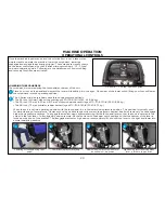
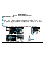
Depress position “A” for 1 second
then depress position “B”
To remove the pad drivers or brushes from your disk unit, locate the automatic off switch on the lower control panel at the rear of the
machine. Depress position “A” for 1 second and then depress position “B”.
For the orbital unit, simply pull off the pad taking care to follow proper safety precautions as indicated on your chemical product label in
regards to coming in contact with solution.
Should the pad or brush show ample wear and have reached their replacement point, simply discard the pad or brush and replace it at the
beginning of your next shift. Brushes should be replaced when the bristle length reaches 3/4 in (19 mm).
Alternatively, if not worn out, you can extend the life of your pad driver, pad or brush by rinsing out any captured debris or sediment and then
hanging it to dry between shifts - a simple step that can lower your cost to clean.
1
2
3
This will “click-off” the pad drivers or brushes.
1
Cleaning tools released by auto on/
off feature
2
Starting at the front corners of the
pad, pull it down & off the
pad driver
3
Summary of Contents for S Series
Page 45: ...45 FRAME ASSEMBLY WITH URETHANE WHEELS...
Page 46: ...46 FRAME ASSEMBLY WITH FOAM FILLED WHEELS...
Page 48: ...48 ON BOARD CHEMICAL INJECTION ASSEMBLY OPTIONAL...
Page 49: ...49 BATTERY ASSEMBLY...
Page 50: ...50 RECOVERY TANK ASSEMBLY...
Page 51: ...51 SQUEEGEE ASSEMBLY S 24...
Page 52: ...SQUEEGEE ASSEMBLY S 28 52...
Page 53: ...SQUEEGEE ASSEMBLY S 32 53...
Page 54: ...54 SQUEEGEE LINKAGE ASSEMBLY...
Page 55: ...55 HEAD LIFT ASSEMBLY...
Page 56: ...56 HEAD ASSEMBLY DRAWING 1 OF 2 S 24...
Page 57: ...57 HEAD ASSEMBLY DRAWING 2 OF 2 S 24...
Page 58: ...58 HEAD ASSEMBLY S 28 DISK...
Page 59: ...59 HEAD ASSEMBLY S 32...
Page 60: ...60 HEAD ASSEMBLY LOWER S 28 ORBITAL...
Page 61: ...61 HEAD ASSEMBLY UPPER S 28 ORBITAL...
Page 62: ...62 CONTROLS ASSEMBLY S 24...
Page 63: ...63 CONTROLS ASSEMBLY S 28 S 32 DISK...
Page 64: ...64 CONTROLS ASSEMBLY S 28 ORBITAL...
Page 65: ...65 CONTROLS ASSEMBLY BATTERYSHIELDTM CHEMICAL INJECTION SYSTEM OPTIONAL...
Page 66: ...66 ELECTRONICS ASSEMBLY S 24...
Page 67: ...67 ELECTRONICS ASSEMBLY S 28 S 32 DISK...
Page 68: ...68 ELECTRONICS ASSEMBLY S 28 ORBITAL...
Page 69: ...69 ELECTRONICS ASSEMBLY BATTERYSHIELDTM...
Page 70: ...70 CHARGER ASSEMBLY ON BOARD...
Page 71: ...WIRING DIAGRAM S 24...
Page 72: ...WIRING DIAGRAM S 28 S 32 DISK...
Page 73: ...WIRING DIAGRAM S 28 ORBITAL...
Page 74: ...WIRING DIAGRAM BATTERYSHIELD OPTIONAL 74...
Page 75: ...WIRING DIAGRAM ON BOARD CHEMICAL INJECTION SYSTEM OPTIONAL 75...


