20
MACHINE OPERATION
OPERATIONAL CONTROLS
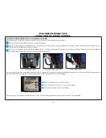
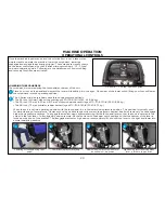
Once the machine is powered on and the solution flow is set, it takes three
simple steps to operate the machine: lower the scrub deck, lower the
squeegee and engage the activation trigger. These steps are visually shown
on the lower control panel by the S-Series mid-size scrubber’s “1, 2, 3-Step”
on-board operation guide. Following are the detail steps of how scrubbing
and recovery functions are activated.
On-board “1, 2, 3-Step” operation guide
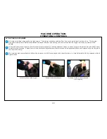
LOWERING THE SCRUB DECK
The scrub deck is lowered using the foot pedal at the rear of the unit.
Lowering scrub head using foot
pedal
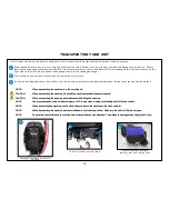
Lower down pressure setting
Place your foot on the pedal and depress the lever while shifting it to the right. Once clear of the lower notch, lifting your foot will lower
the scrub deck into the operating position.
The S-Series mid-size scrubbers have three down pressure settings.
• The 24-inch (610 mm) disk unit has settings of 50, 100 & 140 lb (23, 45 & 64 kg)
• The 28-inch (711 mm) & 32-inch (813 mm) disk scrubbers have settings of 70, 110 & 150 lb (32, 50 & 68 kg)
• The 28-inch (711 mm) orbital scrubber has settings of 70, 110 & 160 lb (32, 50 & 73 kg)
When the unit is set into operating position with the foot pedal, it is in the lower down pressure position. This position is typically used
for daily cleaning of normal soils. However, should you have tough soils or want to perform chemical-free finish removal, you can engage
higher down pressure settings. To engage the medium down pressure setting, lift the foot pedal lever so that the hook is secured in the
cutout in the foot lever. To engage high down pressure, lift the foot lever to the upper notch position so that the bottom of the lever is
locked on the hook of the bracket. To disengage medium or high down pressure, simply lift and shift the lever to the right and lower into
normal operating position.
1
2
1
2
High down pressure setting when
lever is lifted to top position
2
Medium down pressure when lever
is hooked in mid-position
2
Summary of Contents for S Series
Page 45: ...45 FRAME ASSEMBLY WITH URETHANE WHEELS...
Page 46: ...46 FRAME ASSEMBLY WITH FOAM FILLED WHEELS...
Page 48: ...48 ON BOARD CHEMICAL INJECTION ASSEMBLY OPTIONAL...
Page 49: ...49 BATTERY ASSEMBLY...
Page 50: ...50 RECOVERY TANK ASSEMBLY...
Page 51: ...51 SQUEEGEE ASSEMBLY S 24...
Page 52: ...SQUEEGEE ASSEMBLY S 28 52...
Page 53: ...SQUEEGEE ASSEMBLY S 32 53...
Page 54: ...54 SQUEEGEE LINKAGE ASSEMBLY...
Page 55: ...55 HEAD LIFT ASSEMBLY...
Page 56: ...56 HEAD ASSEMBLY DRAWING 1 OF 2 S 24...
Page 57: ...57 HEAD ASSEMBLY DRAWING 2 OF 2 S 24...
Page 58: ...58 HEAD ASSEMBLY S 28 DISK...
Page 59: ...59 HEAD ASSEMBLY S 32...
Page 60: ...60 HEAD ASSEMBLY LOWER S 28 ORBITAL...
Page 61: ...61 HEAD ASSEMBLY UPPER S 28 ORBITAL...
Page 62: ...62 CONTROLS ASSEMBLY S 24...
Page 63: ...63 CONTROLS ASSEMBLY S 28 S 32 DISK...
Page 64: ...64 CONTROLS ASSEMBLY S 28 ORBITAL...
Page 65: ...65 CONTROLS ASSEMBLY BATTERYSHIELDTM CHEMICAL INJECTION SYSTEM OPTIONAL...
Page 66: ...66 ELECTRONICS ASSEMBLY S 24...
Page 67: ...67 ELECTRONICS ASSEMBLY S 28 S 32 DISK...
Page 68: ...68 ELECTRONICS ASSEMBLY S 28 ORBITAL...
Page 69: ...69 ELECTRONICS ASSEMBLY BATTERYSHIELDTM...
Page 70: ...70 CHARGER ASSEMBLY ON BOARD...
Page 71: ...WIRING DIAGRAM S 24...
Page 72: ...WIRING DIAGRAM S 28 S 32 DISK...
Page 73: ...WIRING DIAGRAM S 28 ORBITAL...
Page 74: ...WIRING DIAGRAM BATTERYSHIELD OPTIONAL 74...
Page 75: ...WIRING DIAGRAM ON BOARD CHEMICAL INJECTION SYSTEM OPTIONAL 75...

