16
MACHINE PREPARATION
RECOVERY TANK PREPARATION & PLASTIC BAG HOLDER
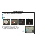
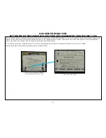
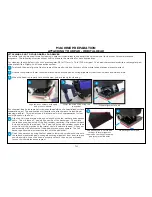
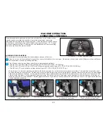
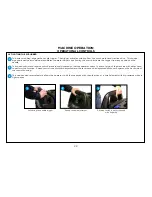
PICKING UP LARGER DEBRIS DURING THE CLEANING PROCESS
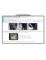
Your S-Series mid-size scrubber has been designed with two hooks molded into the handle that can be
used to hang a plastic bag to put larger pieces of debris that you come across during the cleaning process
or that obstruct the squeegee assembly and cause streaking. Simply slide a handle of the plastic bag over
each of the hooks.
Plastic bag hooks indicated above
1
TREATING YOUR RECOVERY TANK
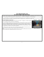
Your S-Series mid-size scrubber has been designed with a debris tray and the TTS tank treatment system. TTS is a treatment system that
utilizes Bromine tablets, typically used in pools and spas, to kill the bacteria in the tank that cause odors. To ensure that TTS is prepared to
treat your recovery tank:
Check the TTS bromine puck
3
Press the TTS holder and bromine
puck back into the debris tray
4
TTS is located in the debris tray
inside the recovery tank
1
Lift the recovery tank lid to the open position and locate the debris tray.
1
Lift the debris tray out and turn it over so that you are able to pinch the two tabs protruding from the underside of the debris tray
together to release the TTS Bromine puck holder.
2
Remove the debris tray
2
Check the size of the Bromine puck. Replace the Bromine puck when it is approximately 25% of it’s original size.
3
Press the TTS holder and bromine puck back into the debris tray.
4
CAUTION: Use Bromine only! Do not use chlorine. Chlorine can interact with ammonia based detergents to cause harmful fumes.
Summary of Contents for S Series
Page 45: ...45 FRAME ASSEMBLY WITH URETHANE WHEELS...
Page 46: ...46 FRAME ASSEMBLY WITH FOAM FILLED WHEELS...
Page 48: ...48 ON BOARD CHEMICAL INJECTION ASSEMBLY OPTIONAL...
Page 49: ...49 BATTERY ASSEMBLY...
Page 50: ...50 RECOVERY TANK ASSEMBLY...
Page 51: ...51 SQUEEGEE ASSEMBLY S 24...
Page 52: ...SQUEEGEE ASSEMBLY S 28 52...
Page 53: ...SQUEEGEE ASSEMBLY S 32 53...
Page 54: ...54 SQUEEGEE LINKAGE ASSEMBLY...
Page 55: ...55 HEAD LIFT ASSEMBLY...
Page 56: ...56 HEAD ASSEMBLY DRAWING 1 OF 2 S 24...
Page 57: ...57 HEAD ASSEMBLY DRAWING 2 OF 2 S 24...
Page 58: ...58 HEAD ASSEMBLY S 28 DISK...
Page 59: ...59 HEAD ASSEMBLY S 32...
Page 60: ...60 HEAD ASSEMBLY LOWER S 28 ORBITAL...
Page 61: ...61 HEAD ASSEMBLY UPPER S 28 ORBITAL...
Page 62: ...62 CONTROLS ASSEMBLY S 24...
Page 63: ...63 CONTROLS ASSEMBLY S 28 S 32 DISK...
Page 64: ...64 CONTROLS ASSEMBLY S 28 ORBITAL...
Page 65: ...65 CONTROLS ASSEMBLY BATTERYSHIELDTM CHEMICAL INJECTION SYSTEM OPTIONAL...
Page 66: ...66 ELECTRONICS ASSEMBLY S 24...
Page 67: ...67 ELECTRONICS ASSEMBLY S 28 S 32 DISK...
Page 68: ...68 ELECTRONICS ASSEMBLY S 28 ORBITAL...
Page 69: ...69 ELECTRONICS ASSEMBLY BATTERYSHIELDTM...
Page 70: ...70 CHARGER ASSEMBLY ON BOARD...
Page 71: ...WIRING DIAGRAM S 24...
Page 72: ...WIRING DIAGRAM S 28 S 32 DISK...
Page 73: ...WIRING DIAGRAM S 28 ORBITAL...
Page 74: ...WIRING DIAGRAM BATTERYSHIELD OPTIONAL 74...
Page 75: ...WIRING DIAGRAM ON BOARD CHEMICAL INJECTION SYSTEM OPTIONAL 75...

