background image

Maintenance

Version 1.0.1  dated 2017-11-16

Page 79

Translation of the original instructions

TX6222

GB

T

X

6222

_GB

_5.

fm

OPTIMUM

M A S C H I N E N   -   G E R M A N Y

®

6.5

Repair

6.5.1

Customer service technician

For any repair work request the assistance of an authorised customer service technician. Con-
tact your specialist dealer if you do not have customer service's information or contact Stürmer 
Maschinen GmbH in Germany who can provide you with a specialist dealer's contact informa-
tion. Optionally, the 
Stürmer Maschinen GmbH
Dr.-Robert-Pfleger-Str. 26
D- 96103 Hallstadt, Germany
can provide a customer service technician, however, the request for a customer service techni-
cian can only be made via your specialist dealer.
If the repairs are carried out by qualified technical personnel, they must follow the indications 
given in these operating instructions.
Optimum Maschinen Germany GmbH accepts no liability nor does it guarantee against damage 
and operating malfunctions resulting from failure to observe these operating instructions.
For repairs, only use

faultless and suitable tools only,

only original parts or parts from series expressly authorised by Optimum Maschinen Ger-
many GmbH.

Summary of Contents for OPTIturn TX 6222

Page 1: ...GB OPTIMUM M A S C H I N E N G E R M A N Y Operating Manual Version 1 0 1 Lathe Part no 3432460...

Page 2: ...er of the headstock 15 1 9 4 Protective covers of drive 15 1 9 5 Lathe chuck protection with position switch 15 1 9 6 Chip guard shield 15 1 9 7 Prohibition warning and mandatory signs 15 1 10 Safety...

Page 3: ...1 Rotational direction 35 4 8 2 Speed 35 4 9 Feed 35 4 9 1 Longitudinal feed selection 35 4 9 2 Cross feed selection 36 4 9 3 Thread selection 36 4 10 Spindle seat Camlock DIN ISO 702 2 36 4 10 1 Fas...

Page 4: ...ing parts 73 6 4 Maintenance 74 6 4 1 Tensioning of drive belt 74 6 4 2 Refilling the cooling lubricant 74 6 4 3 Replacement of the shear pin on the feed rod 74 6 4 4 Adjusting the spindle nut on the...

Page 5: ...manual 117 9 4 Liability claims warranty 118 9 5 Storage 119 9 6 Dismantling disassembling packing and loading 119 9 6 1 Decommissioning 120 9 6 2 Dismantling 120 9 6 3 Disassembly 120 9 6 4 Packing...

Page 6: ...ife In the paragraph Maintenance all maintenance works and functional tests are described which the operator must perform in regular intervals The illustration and information included in the present...

Page 7: ...ion of the country of destination the specific applicable regulations of each country must be observed If applicable necessary measures must be taken to comply with the country specific regula tions b...

Page 8: ...NING A danger that can cause serious injury or death CAUTION A danger or unsafe procedure that can cause personal injury or damage to property ATTENTION Situation that could cause damage to the lathe...

Page 9: ...modified without the approval of Maschinen Germany GmbH then the lathe is being used improperly We will not be held liable for any damages resulting from any operation which is not in accord ance with...

Page 10: ...ng parts Long workpieces must be propped up Use the steady rest or follow rest in conjunction with the tailstock spindle to support longer parts and prevent the workpiece from flapping around and flyi...

Page 11: ...erefore the warning notes refer to both the operation and maintenance of the lathe Determine and indicate clearly who will be responsible for the different activities on the lathe operation maintenanc...

Page 12: ...nce a year regarding all safety standards that apply to the lathe the operation generally accepted engineering standards The operator must also check the personnel s knowledge level document the train...

Page 13: ...health Make sure that the generated health hazardous dusts and mist are safely sucked off at the point of origin and is dissipated or filtered from the working area To do so use a suitable extraction...

Page 14: ...ective cover on the headstock a DC brake of the spindle drive protective covers on the machine bed a safety screw at the tailstock a protective cover on the lead screw an feed rod safety screws for th...

Page 15: ...afety critical protective function in respect of flying parts must be visually inspected at regular intervals by responsible personnel provided by the customer in order to guarantee the operational sa...

Page 16: ...table General check Equipment Check OK Guards Mounted firmly bolted and not damaged Signs Markings Installed and legible Date Checked by signature Functional check Equipment Check EMERGENCY STOP Swit...

Page 17: ...types of work WARNING Before activating the lathe ensure that this will neither endanger other persons nor cause damage to equipment Avoid any unsafe work methods Make sure that your work does not end...

Page 18: ...he by turning off the main switch due to required works e g functional control 1 13 2 Using lifting equipment WARNING The use of unstable lifting and load suspension equipment that might break under l...

Page 19: ...tion of a qualified electrician prior to initial commissioning and after modifications or repairs prior to recommissioning and at set intervals The intervals must be set so that foreseeable defects ca...

Page 20: ...mm 620 Swing diameter in the bed bridge mm 880 Swing diameter over lathe saddle mm 580 Swing diameter over cross slide mm 424 Turning length in the bed bridge mm Spindle nose mm 231 Main spindle bore...

Page 21: ...125 2 10 Coolant equipment Coolant tank 50 litres Pump delivery height m 4 Delivery volume l min 25 Power S1 100 W 2 11 Dimensions Weight of machine kg 2800 2 12 Environmental conditions Temperature...

Page 22: ...s not necessarily a safe working level Though there is a dependency between the degree of the noise emission and the degree of the noise disturbance it is not possible to use it reliably to determine...

Page 23: ...ermined the damage or to take photos of this sta tus Please inform us about any other claims within six days after receipt of delivery Check if all parts are firmly seated 3 2 Interdepartmental transp...

Page 24: ...nd or ship per must be notified immediately so the necessary steps can be taken to register a complaint Inspect the machine completely and carefully making sure that all materials such as shipping doc...

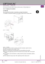
Page 25: ...Y 3 4 2 Crane The machine is lifted with slings The bedslide and the tailstock must be driven to the end of the machine bed in order to achieve a balanced load Clamp tailstock and top slide Wrap arou...

Page 26: ...cted Follow the prescribed safety areas and escape routes according to VDE 0100 part 729 as well as the environmental conditions for the operation of the machine The main switch of the machine must be...

Page 27: ...tly performed commissioning The machine can be placed in three different ways Anchor free assembly with vibration dampers anchored assembly ATTENTION Insufficient rigidity of the ground leads to super...

Page 28: ...m OPTIMUM M A S C H I N E N G E R M A N Y 3 6 2 Vibration free assembly Optional vibration dampers Attaching of 6 pieces SE2 vibration dampers on levelling points between the foundation and machine fo...

Page 29: ...DIN EN 10058 70x20 with anchor rods DIN 529 M12x250 in line with the centres of the levelling points Lift the machine from the floor and fit the anchor rods into each levelling point with the rod cent...

Page 30: ...the carriage on the centre of the bed and using the four end adjusting screws 1 adjust until the machine spirit level displays an approximate value Move the carriage to the headstock and then to the t...

Page 31: ...efore moving the slides Only afterwards can the machine be placed into operation The headstock and feed box oil must be changed 150 hours after being filled for the first time then after every 2000 ho...

Page 32: ...wire connection must be available Main Fuse 16 A ATTENTION Make sure that the direction of rotation of the drive motor and cooling lubricant pump is correct If the rotational direction switch is switc...

Page 33: ...e chuck protection 4 Selector switch feed gear mechanism 8 Machine lamp 7 Chip guard shield 10 Tailstock 9 Digital Position Indicator DP 700 DP700 Quick start guide on page 65 12 Control panel on lath...

Page 34: ...on to the right in order to release the push button Set all of the actuators in the neutral position and close the lathe chuck protection The control lamp 3 for operation must be on 4 4 Switching off...

Page 35: ...e anti clockwise The middle position is the neutral position 0 Move the shift lever up if you want the turning direction to be clockwise ATTENTION Wait until the lathe has come to a complete halt befo...

Page 36: ...wivel gear drive to 7 Set the both selection lever and on swivel gear drive to M Set the selection lever to 4 9 3 Thread selection Set the selector lever for the thread to be cut according to the symb...

Page 37: ...p bolt marks 4 10 2 Adjusting the Camlock bolts to the workpiece holder Insert all of the bolts in the screwed flange of the chuck until the reference mark the circular reference line F is in line wit...

Page 38: ...hen the machine is at a standstill The reference speed applies for jaws mounted inside in tiers whereby they must not protrude past the outer diameter of the chuck At the determined reference speed 1...

Page 39: ...malfunctions with significantly reduced tensioning force which affects the accuracy and causes excessive wear and seizing Lubricate the installed lathe chuck at least once per week The used lubricant...

Page 40: ...letely covers the protruding workpiece between the tips CAUTION Long workpieces must be additionally supported They are supported by the tailstock sleeve and if necessary a rest with a lathe dog CAUTI...

Page 41: ...both plain machined faces of the workpiece Img 4 3 Turning between centres The lathe dog is clamped onto the workpiece The driving bolt which is screwed into the flange for the lathe chuck transmits t...

Page 42: ...aper and the taper of the centring point Push the fixed MT5 center with reducing cone MT5 obtained in your delivery into the inter nal taper of the spindle holding fixture 4 14 Mounting of rests 4 14...

Page 43: ...imited First detach the fastening screws and then pull out the dowel pins For re assembly proceed the other way around 4 16 General operating instructions 4 16 1 Longitudinal turning In the straight t...

Page 44: ...addle using the tightening screw 4 16 4 Tailstock The tailstock quill is used to hold the tools bits centres etc Clamp the required tool into the quill of the tailstock Use the scale on the sleeve to...

Page 45: ...turning Switch on the feed rod 1 INFORMATION The feed rod drive can only be switched on if the gearbox levers are in the right position By switching on the drive the magnetic coupling of the feed rod...

Page 46: ...sitions have been set the lathe saddle moves towards the lathe chuck In order for the lathe saddle to move toward the tailstock the feed direction control handle 2 on headstock has to be in the right...

Page 47: ...oss adjustment of the tailstock Clamp the tailstock by moving the clamping handle forwards L INFORMATION Example A 300mm long shaft is to be taper turned between the centres with an angle of 1 Cross a...

Page 48: ...xed unit stop and the bedslide Put the gauge with stand on the lathe bed and horizontally align the test prod with the test prod with thetop slide 90 to the top slide The twisting measure is calculate...

Page 49: ...p slide is twisted in a way that the gauge does not indicate any travel of the pointer over the whole length of the cone offset over the handwheel of the top slide Then you may start reaming the lathe...

Page 50: ...is clamped between the points The stand with the gauge is put on the bedslide The gauge is aligned 90 to the rotation axis and horizontally brought into contact with the shaft The gauge will pass alon...

Page 51: ...wing pages Cutting speeds on page 63 Criteria of the cutting conditions Cutting speed Vc m min Depth of cut ap mm Infeed f mm rev Cutting speed In order to get the speed for the machine settings of th...

Page 52: ...n turned to the diameter of the desired thread The workpiece requires a chamfer at the beginning of the thread and an undercut at the thread run out The speed must be as low as possible The thread cut...

Page 53: ...ave been turned to the diameter of the desired thread The workpiece requires a chamfer at the beginning of the thread and an undercut at the thread run out The speed must be as low as possible The thr...

Page 54: ...this way the thread cutting tool cuts only on one thread flank with each passage Do not execute any more free cutting just before reaching the full thread depth 4 22 4 Multiple layered threads A mult...

Page 55: ...OPTIMUM M A S C H I N E N G E R M A N Y ISO trapezoid thread one and multi ple threaded TR Tr 40 x 7 Tr 40 x 14 P7 Motion thread Leading spindle and transport spindle Round thread RD RD DIN 405 Fitti...

Page 56: ...2 0 043 1 1 M 1 6 0 35 1 373 1 171 1 221 0 215 0 189 0 051 1 3 M 1 8 0 35 1 573 1 371 1 421 0 215 0 189 0 051 1 5 M 2 0 4 1 740 1 509 1 567 0 245 0 217 0 058 1 6 M 2 2 0 45 1 908 1 648 1 713 0 276 0 2...

Page 57: ...r d2 D2 Core diameter Bolts Nut Bolt Nut M2 x 0 2 1 870 1 755 1 783 M16 x 1 5 15 026 14 160 14 376 M2 5 x 0 25 2 338 2 193 2 229 M20 x 1 19 350 18 773 18 917 M3 x 0 35 2 773 2 571 2 621 M20 x 1 5 19 0...

Page 58: ...reads are larger in their diameter as BSW Desig nation 1 8 28 BSP BSPT BSPT British Standard Pipe Taper Thread Conic tube thread cone 1 16 designation 1 4 19 BSPT BA BA British Association Standard Th...

Page 59: ...feed direction towards the clamping chuck is selected and the machine spindle turns to the right the turning direction of the machine spindle is determined when you look into the spindle from the rear...

Page 60: ...the tool The tool should be cooled during the milling process Cooling the tool with a suitable cooling lubri cant ensures better working results and a longer service life of the cutting tool Switch th...

Page 61: ...a and fungal decay Cooling lubricants and tanks on page 80 We would like to ask you to have the following machine related properties of the cooling lubri cant confirmed in writing by the manufacturer...

Page 62: ...Operation Version 1 0 1 dated 2017 11 16 Page 62 Translation of the original instructions TX6222 GB TX6222_GB_4 fm OPTIMUM M A S C H I N E N G E R M A N Y...

Page 63: ...5 2 Influences on the cutting speed vc Cutting speed in m min t Service life in min The service life t is the period of time in minutes during which the cutting insert performs cutting tasks until it...

Page 64: ...ant steel 600 700 P 10 80 75 71 71 67 63 56 53 50 50 47 5 45 45 42 5 40 33 5 33 5 31 5 31 5 30 28 Tool steel 1500 1800 High speed steel 9 7 5 6 5 6 4 5 3 6 4 3 2 2 5 P 10 45 42 5 40 40 37 5 35 5 35 5...

Page 65: ...xternal switch mode Output voltage 15VDC Input Voltage to DP700 15 24VDC 10 Conforms to Low Voltage Directive External PSU Input Note Newall Measurements Systems reserves the right to change specifica...

Page 66: ...Key Clear Numeric Entry Centre Find Undo Key Digifind Reference Switches between Zero and Axis Preset modes Switches between Absolute and Incremental modes Information selection scrolls through optio...

Page 67: ...re details of axis 1 of axis 1 user defined use numeric keypad to enter value value is in whole minutes of axis 1 to scroll through functions to return to main menu See full manual on website for more...

Page 68: ...r remove chips or clean the working area of the lathe with compressed air Cleaning inside the working area using compressed air may cause damages to the lathe 6 1 Safety WARNING The consequences of in...

Page 69: ...check that there is no danger for persons and that the lathe is not damaged 6 2 Inspection and maintenance The type and level of wear depends to a large extent on the individual usage and operating c...

Page 70: ...tenterhook to pull out long cips Apron Check oil quantity Check the oil level in the apron Check the oil level using the inspection window Level max until the middle of the above inspection window Th...

Page 71: ...r and headstock Check the oil level using the inspection window Level max until the middle of the inspection window For the first time after some operating hours according to demand V belt Spindle dri...

Page 72: ...crew from the drain hole Unscrew the screw from the filler hole Close the drain hole if no more oil drains Fill up to the middle of the reference mark of the oil sight glass into the filler hole using...

Page 73: ...81 When necessary Tailstock tighten If the tailstock clamping wears off Shorten the clamping distance by adjusting the nut below the tailstock based on operator s historic values Electronics Electrica...

Page 74: ...olant tank through the working area of the lathe The machine is lacquered with a one component paint Observe this fact when selecting your cooling lubricant and cleaning of the machine A one component...

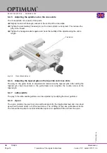
Page 75: ...4 4 Adjusting the spindle nut on the top slide The spindle nut consists of two parts Loosen the axial securing screw next to the spindle nut Turn the spindle in clockwise direction until the spindle...

Page 76: ...entire length Img 6 6 Cross slide spindle nut 6 4 6 Adjusting the tapered gibs on the top slide and cross slide The play on the guide tracks is adjusted and reduced via the tapered gibs After setting...

Page 77: ...e of a lathe chuck can decrease by up to 50 percent of the nominal tensioning force A presumably securely clamped workpiece can then fall out of the chuck during processing Lubricate the lathe chuck L...

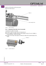
Page 78: ...the headstock if the workpiece tapers while turning the shaft Img 6 8 Headstock Img 6 9 Headstock Clamp a precisely machined precisely ground test shaft with a length of 300 mm Attach a dial gauge on...

Page 79: ...nally the St rmer Maschinen GmbH Dr Robert Pfleger Str 26 D 96103 Hallstadt Germany can provide a customer service technician however the request for a customer service techni cian can only be made vi...

Page 80: ...more than 10 6 ml there is an increase in nitrite content to more than 20 ppm mg 1 or nitrate content to more than 50 ppm mg 1 there is an increase in the N nitrosodiethanolamine NDELA to more than 5...

Page 81: ...creases 0 5 based on initial filing Measures in accordance manufacturer s rec ommendations 1 0 based on initial filing Replace cooling lubricant clean cooling lubri cant circulation system Usage conce...

Page 82: ...ines name Herstellungsdatum Date of manufacture Artikelnummer Article no Die Artikelnummer befindet sich in der Ersatzteilliste The article no is located in the spare parts list Die Seriennummer befin...

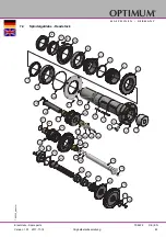
Page 83: ...iebsanleitung TX6222 DE EN TX6222_parts fm OPTIMUM M A S C H I N E N G E R M A N Y 7 4 Spindelgetriebe Headstock 8 5 12 9 16 15 145 116 14 7 6 146 115 145 2 13 11 3 10 4 17 155 60 61 62 61 63 65 64 57...

Page 84: ...iebsanleitung TX6222 DE EN TX6222_parts fm OPTIMUM M A S C H I N E N G E R M A N Y Spindelgetriebe Headstock 52 84 79 83 78 35 82 77 29 29 83 48 81 80 118 52 149 29 43 44 42 41 40 48 39 45 46 49 51 47...

Page 85: ...22 DE EN TX6222_parts fm OPTIMUM M A S C H I N E N G E R M A N Y Spindelgetriebe Headstock 87 105 90 89 112 113 145 96 164 98 150 97 91 152 156 88 99 85 105 145 90 89 99 156 106 108 97 107 100 148 101...

Page 86: ...6 86 Originalbetriebsanleitung TX6222 DE EN TX6222_parts fm OPTIMUM M A S C H I N E N G E R M A N Y Spindelgetriebe Headstock A A 133 127 129 132 130 131 130 128 141 136 140 135 139 137 138 142 143 13...

Page 87: ...be Washer 1 DIN 125 A 10 5 35 Wellendichtring Seal 2 DIN 3760 A 32 x 45 x 7 36 Scheibe Washer 1 DIN 125 A 21 37 Federring Spring ring 1 DIN 128 A20 38 Sechskantmutter Hexagon screw 1 ISO 4032 M20 39 W...

Page 88: ...Flange 1 034324601118 119 Verschlussschraube Plug screw 2 034324601119 121 Fangblech Baffle plate 1 034324601121 122 Abdeckung Cover 1 034324601122 123 Buchse Bushing 1 034324601123 124 Abdeckung Cov...

Page 89: ...eckung Cover 1 034324601159 160 Zahnriemen Gear belt 1 480 8M20 034324601160 161 Scheibe Washer 3 DIN 125 A 17 162 Innensechskantschraube Socket head screw 3 ISO 4762 M16 x 50 163 Spannstift Spring pi...

Page 90: ...H I N E N G E R M A N Y 7 5 Vorschubgetriebe Feed gear 136 133 135 135 132 147 135 143 135 105 105 108 104 134 145 107 106 100 99 103 101 102 110 103 109 130 100 99 123 121 123 121 120 119 128 119 11...

Page 91: ...S C H I N E N G E R M A N Y 7 6 Vorschubgetriebe Feed gear 66 54 59 53 13 55 65 56 57 64 58 52 93 68 69 70 71 80 72 73 74 75 76 77 78 79 137 81 93 67 92 83 84 86 87 85 90 89 96 96 82 91 16 3 2 9 14 4...

Page 92: ...g ring 1 DIN 471 50x2 35 Innensechskantschraube Socket head screw 3 ISO 4762 M4 x 16 36 Innensechskantschraube Socket head screw 3 ISO 4762 M4 x 10 37 Innensechskantschraube Socket head screw 3 ISO 47...

Page 93: ...over 1 034324603114 115 Geh use Housing 1 034324603115 116 Schaltgabel Switch fork 2 034324603116 117 Welle Shaft 1 034324603117 118 Welle Shaft 1 034324603118 119 Exzenter Eccentric 2 034324603119 12...

Page 94: ...nleitung TX6222 DE EN TX6222_parts fm OPTIMUM M A S C H I N E N G E R M A N Y 7 7 Schlosskasten Apron 1 29 33 16 29 32 15 21 27 29 26 20 28 27 12 48 9 31 30 24 22 17 35 5 10 34 33 14 33 29 40 39 38 18...

Page 95: ...er 1 03432460425 26 Innensechskantschraube Socket head screw 9 ISO 4762 M6 x 16 27 Axiallager Thrust bearing 2 03432460427 28 Nadelager Needle bearing 1 03432460428 29 Nadelager Needle bearing 4 03432...

Page 96: ...2 DE EN TX6222_parts fm OPTIMUM M A S C H I N E N G E R M A N Y 7 8 Planschlitten Bettschlitten Cross slide bed slide 26 19 27 39 38 40 41 38 39 19 38 11 18 8 9 35 37 38 39 2 37 10 35 36 4 3 5 17 42 3...

Page 97: ...22 Platte Plate 2 034324605 22 23 Platte Plate 2 034324605 23 24 Abstreifer Wiper 1 034324605 24 25 Abstreifer Wiper 1 034324605 25 26 Planschlitten Cros slide 1 034324606 26 27 Keilleiste Gib 1 0343...

Page 98: ...hrung Guide 1 03432460713 14 Keilleiste Gib 1 03432460714 15 Welle Shaft 1 03432460715 16 Oberschlitten Top slide 1 03432460716 17 Innensechskantschraube Socket head screw 2 ISO 4762 M8 x 20 18 Innen...

Page 99: ...n 1 0 1 2017 11 16 99 Originalbetriebsanleitung TX6222 DE EN TX6222_parts fm OPTIMUM M A S C H I N E N G E R M A N Y 7 10 Sp neschutz Chip safety 8 15 24 1 46 45 43 42 38 33 34 30 28 20 36 41 29 27 26...

Page 100: ...17 11 16 100 Originalbetriebsanleitung TX6222 DE EN TX6222_parts fm OPTIMUM M A S C H I N E N G E R M A N Y 7 11 Antrieb Unterbau Drive substructure A A 373 383 11 384 12 587 10 5 580 3 571 577 574 57...

Page 101: ...albetriebsanleitung TX6222 DE EN TX6222_parts fm OPTIMUM M A S C H I N E N G E R M A N Y 7 12 Maschinenbett Machine bed A 32 7 35 6 2 13 14 567 18 17 53 568 568 569 147 22 21 199 21 595 104 19 61 21 5...

Page 102: ...2460814 15 Abdeckung Cover 1 03432460815 16 Abdeckung Cover 1 03432460816 17 Leitspindel Lead spindle 1 03432460817 18 Zugspindel Feed spindle 1 03432460818 19 Lagerbock Bearing block 1 03432460819 20...

Page 103: ...32460864 104 Schmiernippel Lubrication cup 3 034324608104 147 Passfeder Fitting key 2 034324608147 199 Innensechskantschraube Socket head screw 19 ISO 4762 M8 x 25 322 Feder Spring 12 034324608322 373...

Page 104: ...104 Originalbetriebsanleitung TX6222 DE EN TX6222_parts fm OPTIMUM M A S C H I N E N G E R M A N Y 7 14 Reitstock Tailstock 2 39 5 6 24 23 15 16 22 11 19 26 7 28 8 38 42 9 28 43 25 10 41 40 30 31 14 1...

Page 105: ...t 1 03432460917 18 Scheibe Washer 1 03432460918 19 Klemmhebel Clamping hebel 1 03432460919 20 Aufnahme Collet 1 03432460920 21 Handrad Handle 1 03432460921 22 Bolzen Bolt 1 03432460922 23 Welle Shaft...

Page 106: ...Plate 1 0343246010 04 5 Buchse Bushing 3 0343246010 05 6 Endanschlag Limit stop 2 0343246010 06 7 Schraube Screw 2 0343246010 07 8 Buchse Bushing 3 0343246010 08 9 Kugellager Ball bearing 3 6001 0406...

Page 107: ...Bezeichnung Designation Menge Gr sse Artikelnummer Qty Size Item no 1 H lse Sleeve 2 034324601101 2 Gewindebolzen Theaded bolt 3 034324601102 3 R ndelmutter Knurled nut 4 034324601103 4 Messingspitze...

Page 108: ...erteil Top part 1 034324601201 2 Klemmplatte Clamping plate 1 034324601202 3 H lse Sleeve 3 034324601203 4 Messingspitze Brass tip 3 034324601204 5 Gewindebolzen Threaded bolt 3 034324601205 6 R ndelm...

Page 109: ...Ersatzteile Spare parts Version 1 0 1 2017 11 16 109 Originalbetriebsanleitung TX6222 DE EN TX6222_parts fm OPTIMUM M A S C H I N E N G E R M A N Y 7 18 Schaltplan Wiring diagram...

Page 110: ...Ersatzteile Spare parts Version 1 0 1 2017 11 16 110 Originalbetriebsanleitung TX6222 DE EN TX6222_parts fm OPTIMUM M A S C H I N E N G E R M A N Y...

Page 111: ...Ersatzteile Spare parts Version 1 0 1 2017 11 16 111 Originalbetriebsanleitung TX6222 DE EN TX6222_parts fm OPTIMUM M A S C H I N E N G E R M A N Y...

Page 112: ...itch 03464040SQ5 3S1 Not Halt Schlagschalter Emergency stop button 034640403S1 3K1 Relais Sicherheitssteuerung Safety control relay 034640403K1 3K2 Relais Sicherheitssteuerung Safety control relay 034...

Page 113: ...Meropa 150 VG 100 CLP 100 Aral Degol BG 100 BP Energol GR XP 100 SPARTAN EP 100 Kl beroil GEM 1 100 Mobilgear 627 Shell Omala 100 Meropa 100 VG 68 CLP 68 Aral Degol BG 68 BP Energol GR XP 68 SPARTAN...

Page 114: ...pour broches haute vitesse VG 68 Deol BG 68 Emergol HLP D68 Spartan EP 68 Druck l KLP 68 C Shell Omala 68 Fett f r Zentralschmierung Flie fett Grease for central lubrica tion Graisse pour lubrificati...

Page 115: ...if neces sary Gear positions on feed gear can not be switched Gear is switchable but no feed Sliding gear drive feed Change gear bar not engaged Check shift pins in the feed gear Check change gear ba...

Page 116: ...mall heat buildup Grinding cracks due to improper cool ing Excessive play in the spindle bear ings oscillations occur Set greater wedge angle Cool uniformly Have the clearance in the spindle bearing a...

Page 117: ...nut Split nut which engages the lead screw Lathe chuck Clamping tool for holding the workpiece Drill chuck Drill bit adapter Lathe saddle Slide on the slideway of the machine bed which feeds parallel...

Page 118: ...ranty claims Using the product beyond the technical options and proper use in particular due to over straining of the machine Any defects arising by one s own fault due to faulty operations or if the...

Page 119: ...contact your municipal waste manage ment If appropriate call on the help of a specialist waste disposal company for the treatment of the material Please make sure that electrical components are dispos...

Page 120: ...and packaging aids from the machine are recyclable and gener ally need to be supplied to the material reuse The packaging wood can be supplied to the disposal or the reuse Any packaging components ma...

Page 121: ...this product will protect the environment and the public health Incorrect disposal constitutes a risk to the environment and public health Recycling of material will help reduce the consumption of ra...

Page 122: ...lathe without numerical control The following other EU Directives have been applied EMC Directive 2014 30 EC The following harmonized standards were applied EN ISO 23125 2015 Machine tools Safety Tur...

Page 123: ...rning and recessing 44 I Inch thread 58 Indexable inserts 59 Installation plan 27 L Lathe chuck protection 15 Lifting equipment 18 Longitudinal turning 43 Lubrication 31 M Main switch 14 Maintenance 6...

Page 124: ...he original instructions TX6222 GB OPTIMUM M A S C H I N E N G E R M A N Y 10 DP700 Digital readout The detailed manual is available as a download http www newall co uk support downloads digital_reado...

Reviews: