


3 Check and start operation
3-1 The name and function for the operation and display
BU150R
37
3
* "Setting" switch 4 is valid when the auto startup after recovery from power failure setting
("Setting" switch 2) is set to OFF (auto restart is performed).
* This setting mode is valid only after the UPS has been stopped by the contact signal
backup stop signal (BS).
* When a cable is connected to the RS232C port and the UPS monitoring software is
used, the unit operates in Mode A regardless of this setting.
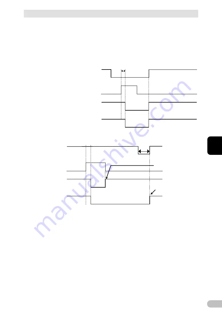
1) When BS signal is used to stop the UPS after a power failure occurs.
2) When BS signal is used to shut down the UPS when AC input is ON
*1 For 10 seconds as a default setting.
AC input
Power output
(Setting switch 4 OFF:
Mode A)
Power output
(Setting switch 4 ON:
Mode B)
ON
OFF
ON
OFF
ON
OFF
ON
OFF
BS signal
*1
1 sec
AC input
Power output
(Setting switch 4 OFF:
Mode A)
Power output
(Setting switch 4 ON:
Mode B)
BS signal
*1
Starts up when BS signal
turns OFF
Starts up whenAC input
turns from OFF to ON
ON
OFF
ON
OFF
ON
OFF
ON
OFF
Summary of Contents for BU150R
Page 22: ...2 Installation and connection 2 1 Installation BU150R 22 Incorrect Positions...
Page 92: ...7 How to use option cards 7 3 SNMP Web card BU150R 92 7 3 SNMP Web card LAN 10 100...
Page 102: ...10 References 10 2 Dimensions BU150R 102 Stand for vertical layput 200 200 70 50 70 50...
Page 103: ...10 References 10 2 Dimensions BU150R 103 10 Rubber feet 23 25 405 50 40 358 40 3...
Page 104: ...10 References 10 2 Dimensions BU150R 104 Using Ear brackets 44 5 22 0 13 5 455 25 465...


