Page 26
DH1 BASE UNIT / DH2 WIRELESS GATEWAY
USER GUIDE
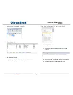
f.
Modify
Template
to desired settings
Exported tags will automatically be added to the Modbus Mapping Table
i.
Fahrenheit
: Temperature Unit
ii.
Celsius
: Temperature Unit
iii.
Battery Voltage
: Indicates Battery level: ≥ 2.9 V is good
iv.
RF Timeout
: 0 = RF OK ; 1 = RF Transmission Failure
v.
RSSI Value
: Received Signal Strength Indication (Transmitter to
Gateway)
1.
Excellent signal = 40-75; Good signal = 76-90; Weak
signal = 91-115
2.
No signal = 0 (When RF times out, RSSI reports 0)
vi.
RF Refresh
: Valuable RF data for trending purposes
vii.
Firmware Version
viii.
Error Code
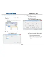
g.
Click
Apply
h.
Click
Close
to exit Template window
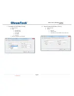
i.
Click
Next
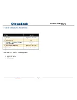
Battery Depletion Chart from 2.9 V
Battery Voltage
Tx Interval
Duration Before Failure
2.9 V
1-second
1 hour
2.9 V
1-minute
2 days
2.9 V
5-minute
10 days
2.9 V
10-minute
20 days
2.9 V
15-minute
30 days
NOTE:
Once a new Battery Pack is installed, it is perfectly normal to get a reading of
3.2 to 3.3 V. This is due to the fact that the WT Series Transmitters take battery level
while it is under load, providing a reliable method of monitoring battery health.
Using the RF Timeout and RF Refresh tags along with battery voltage for monitoring
device and RF communication health is strongly recommended.
If a new Battery Pack has been kept under storage or initially installed, battery level
may need to be read a couple of times to ensure a stable accurate reading.
Replace Battery if reading is less than 2.9 V.
Controlled Copy

