background image

         Construction Manual 

www.oldschoolmodels.com 

Page 11

Step 53 - Wing Assembly (join wing halves)

Test fit the wing halves together one last time and sand as necessary 

for a good fit. 

After test fitting, join the wing halves permanently with 30 minute 

epoxy. Remove the dihedral brace and apply the epoxy into the 

pockets in each wing half and also coat the faces of each root rib.

Slide all the dihedral brace into one of the wing halves, then slide 

remaining wing half in place. Using a couple of clamps (or tape), 

hold wing halves firmly together. Wipe off any excess epoxy and 

remove the clamps only after the epoxy has fully cured.

Remember, any twist in the alignment of the panels cannot be 

fixed after the epoxy cures and will lead to a poor flying model.

This completes assembly of the Kaos 60 wings.

Now it’s time to start construction of the tail surfaces.

Prepare your work area

Now tape the elevator/stab plan and a fresh piece of waxed paper 

on your building board. 

Step 54 - Horizontal Stab Assembly (trailing edge)

Locate a 1/4” x 1/2” x 36" balsa 

strip, measure and cut a piece 

to form the trailing edge of the 

horizontal stab as shown on the 

plans. Pin this piece in position, 

using a straight edge to make sure 

it's straight along it's entire length.

Step 55 - Horizontal Stab Assembly (S1)

Locate both S1s from BP1.These are 

glued to the trailing edge as noted 

on the plans.

Glue one S1 in place first, then the 

other S1 on top, making sure they 

are perfectly aligned.

Step 56 - Horizontal Stab Assembly (S2)

Locate four S2s from BP1 and BP2.

These are glued to the outer edges 

of the trailing edge, two on each 

side.

Glue one S2 in place first, then the 

other S2 on top , making sure they 

are perfectly aligned.

Then do the same for the opposite 

end.

Step 57 - Horizontal Stab Assembly (leading edge)

Next is to cut and install the 

leading edge pieces. Check 

your scrap pile to see if you 

have the proper length first, 

but if not, use an uncut length 

of 1/4” x 1/2” x 36" balsa strip. 

Glue these in position.

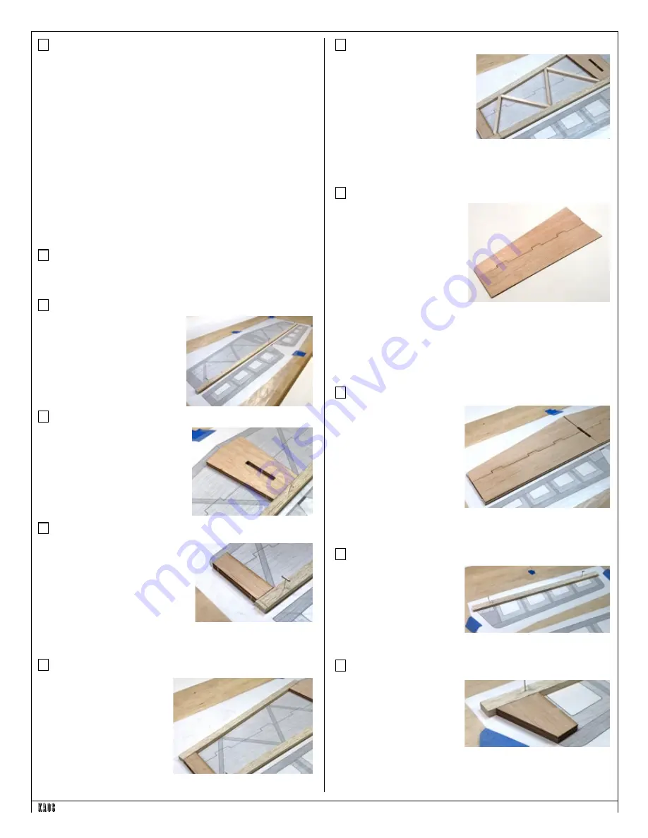
Step 58 - Horizontal Stab Assembly (internal bracing)

Locate a length of 1/4" square 

balsa stick. Use this to cut the 8 

internal brace pieces, 4 on each 

side. Take some extra time to get 

the angles correct to help the 

glue do it's job.

Carefully run a sanding block 

over this framing assembly to make sure it's perfectly flat.

Step 59 - Horizontal Stab Assembly (outer sheeting)

Locate four ES1 and four ES2 

from BP8. An ES1 and ES2 are 

glued together to form a half 

sheet as shown here. 

These pieces will properly only 

fit together one way.

When edge gluing the 

sheeting pieces together, first 

make sure the edges fit first. 

When the adhesive is applied, place the sheeting on the waxed 

paper, so that it’s flat (as shown in the photo). Hold it flat with a 

weight until it's cured to make sure it stays flat. When cured, you’ll 

now have a single piece of sheeting.

Do this 3 more times to create 4 sheeting halves.

Step 60 - Horizontal Stab Assembly (outer sheeting)

Take two of the sheeting 

halves from the previous 

step and glue them to the 

top of the elevator framing.

When cured, remove the 

assembly, flip it over and 

give the open framework a 

quick sand just as you did 

before.

Then apply the remaining two sheeting halves to complete the 

elevator.

Step 61 - Elevator Assembly (outer sheeting)

Next is to cut and install the 

leading edge pieces of the 

elevator. Check your scrap 

pile to see if you have the 

proper lengths first, but if 

not, use an uncut length of 

1/4” x 1/2” x 36" balsa strip. Pin these in position.

Step 62 - Elevator Assembly (S3)

Locate four S3s from BP1 

and BP2. These are glued 

to the inner edges of the 

leading edge, two on each 

side.

Glue one S3 in place first, 

then the other S3 on top , 

making sure they are perfectly aligned.

Then do the same for the other elevator half.

Summary of Contents for Kaos

Page 1: ...atteries wheels etc throughout the building process You must correctly install all R C and other components so that the model operates correctly on the ground and in the air Installation shown in the...

Page 2: ...t 1 4 x 4 x 24 balsa 4 BP8 laser cut 1 16 x 4 x 24 balsa 2 BP9 laser cut 1 16 x 4 x 24 balsa 2 BP10 laser cut 1 16 x 4 x 24 balsa 2 BP11 laser cut 1 16 x 4 x 24 balsa 2 BP12 laser cut 1 16 x 4 x 24 ba...

Page 3: ...anual and online All photos shown in this manual are of different Kaos 60 prototypes Several pieces may have changed slightly with improvements we ve made so parts may look a little different in some...

Page 4: ...to the front and the rear jig dowels Make sure you slide them on in numerical order and pay attention to their orientation The etched rib number should be at the top when properly placed Group the R1...

Page 5: ...along the wing Step 9 Wing Assembly SW2 Locate two SW2s from LP1 and LP2 These are installed the same way as the previous SW pieces just doing it twice You are paying attention to where those etched...

Page 6: ...ood to get it to fit into the slots It is a tight fit Once you re satisfied with how it fits remove it then glue it in position to each rib and to where it contacts the upper portions of SW1 and SW2 M...

Page 7: ...apply a touch of upward pressure where the jig s dowels snap into the J2 and J4 jigs You should find that the dowels pop out and you re left with an assembly that can be flipped over Before popping th...

Page 8: ...ghtly sand the trailing edge so it will continue the airfoil shape Step 33 Wing Assembly dowels Now it s time to mark and drill the leading edge to accept the wing hold dowel Using the two 1 4 pre cut...

Page 9: ...it to length giving yourself a 1 4 or so extra on each end This is used as the bottom spar and will fit into the top cutout of each rib It is STRONGLY recommended that you dry fit this first You might...

Page 10: ...sure everything fits properly and the root ribs in each wing half are touching along their entire length when assembled into a single wing Take your time and get a good fit that doesn t require a lot...

Page 11: ...ding edge Next is to cut and install the leading edge pieces Check your scrap pile to see if you have the proper length first but if not use an uncut length of 1 4 x 1 2 x 36 balsa strip Glue these in...

Page 12: ...fore to complete the elevator halves Prepare your work area Now tape the vertical fin rudder plan and a fresh piece of waxed paper on your building board Step 69 Vertical Fin Assembly VF1 VF2 VF3 Loca...

Page 13: ...as the glue cures Step 80 Fuselage Assembly F5 Locate F5 from LP5 This is attached to the rear of TR4 as shown here Pay attention to the orientation Again make sure it s held at a 90 angle to TR4 as...

Page 14: ...form the fuselage side sheeting Refer to the diagram on the fuselage plan sheets on how these notch together You ll use the same techniques that you used when edge gluing sheeting together for the wi...

Page 15: ...osition but the middle of F2 should line up with the middle of the F2 on the plans Basically what we re looking for here is the fuselage to be lined up on the centerline of the plans as well as front...

Page 16: ...106 Fuselage Assembly stab supports Using scrap 1 4 square balsa cut 4 supports for the stab These will be glued where the stab contacts the inner surface of the fuselage sides You ll glue two on the...

Page 17: ...t works of art and match each other exactly Smooth out the edges of the fuselage Because of the 1 8 sheeting and the 1 8 basswood support installed around the fuselage s perimeter you can be a little...

Page 18: ...artially pushed up through the white mounting block Slip the steering arm in place then push the nose gear wire all the way through the arm and the block Stop when the wire is flush with the top of th...

Page 19: ...a bit of medium CA glue to permanently glue the joiner into both halves making sure the completed leading edge of the elevator is perfectly straight and flat Control horns servo pushrod installation...

Page 20: ...he entire airframe with the covering finish of your choice Note that if you re powering with an electric motor you ll need to make a hole for the cooling air to escape the bottom of the fuselage near...

Page 21: ...ans rather than making large changes electronically at the radio By moving the position of the clevis at the control horn toward the outermost hole you will decrease the amount of control throw of the...

Page 22: ...Page 22 www oldschoolmodels com Construction Manual...

Page 23: ...Construction Manual www oldschoolmodels com Page 23...

Page 24: ...Page 24 www oldschoolmodels com Construction Manual...

Reviews: