background image

         Construction Manual 

www.oldschoolmodels.com 

Page 5

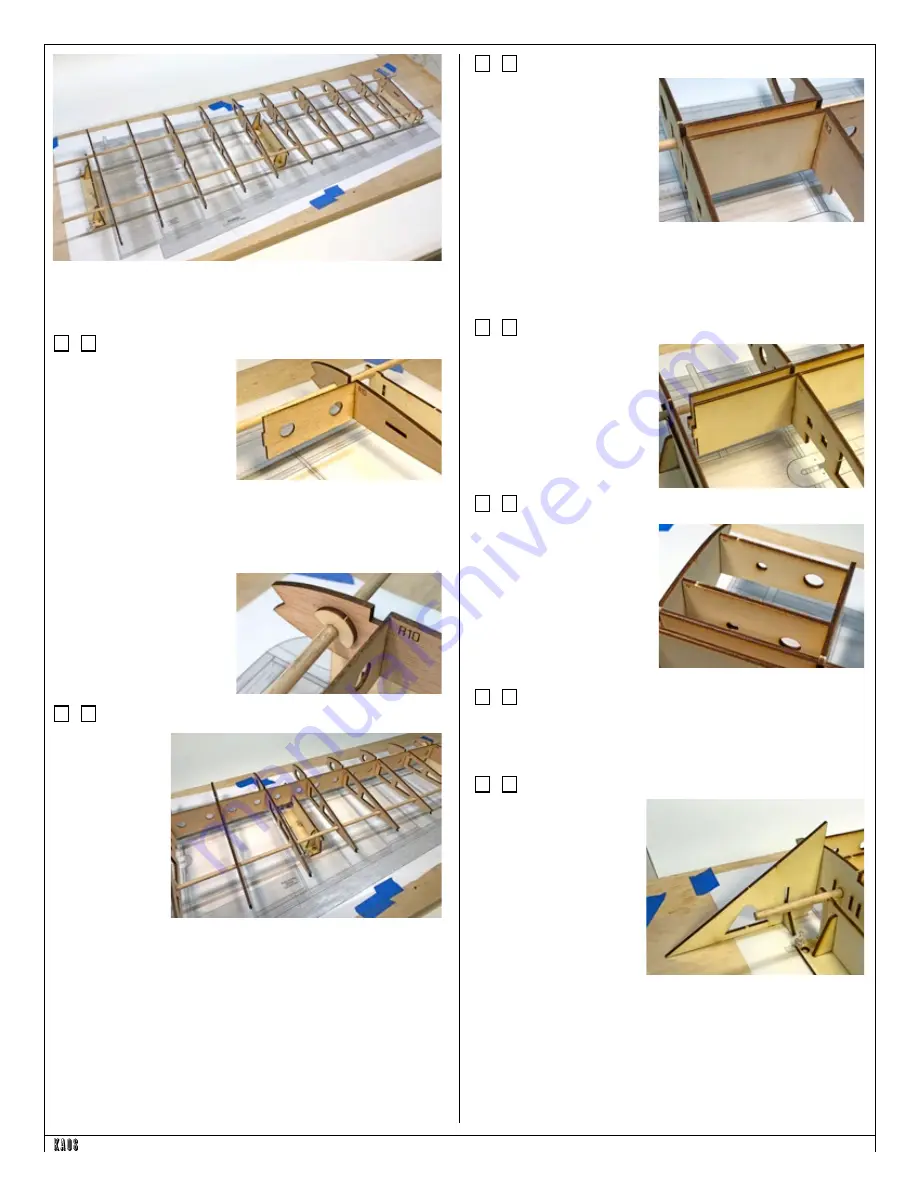
and the R6-R10 to the right side of the middle jig.

Now, snap the dowels on to the jig supports. Then carefully space 

the ribs apart, to their proper locations as shown in the photo.

Step 7 - Wing Assembly (R10 & SW9)

Locate one SW9 from 

BP11. Note that this has an 

engraved circle, as do all of 

the sheer web pieces. This 

circle designates the top and 

should also be positioned 

towards the root rib (R1).

Glue SW9 to R10, making 

sure SW9's tab is completely pushed into the corresponding slot in 

R10. Also make sure the outer edge of SW9 contacts R10 along it's 

entire height. Hold this away from the J2 jig until the glue cures. 

Once cured, then push R10 against J2.

To help hold R10 (and any of 

the other ribs) in place, there's 

a bunch of J8's cut into LP1. 

Wick thin C/A into any of 

these you use first, then snap 

them on to the dowel and use 

them as a "stop".

Step 8 - Wing Assembly (SW3-SW8)

Locate one set of 

SW3-SW8 sheer 

webs from BP13.

Starting with R9, 

you will attach 

each of the 

appropriate SW 

pieces (as noted 

on the plans) 

and glue them 

together as shown 

here. You can 

either do one at a time, or position everything in place, then glue 

everything together at once.

Regardless of how you do it, make sure all of the SW circles are 

positioned properly and their tabs are completely inserted into the 

each rib's tab cutout before gluing. Also make sure that ribs are 

aligned to the plan (remember to use the triangles we talked about 

in step 1).

Even small errors here can multiply as you go along the wing and 

causing larger and larger misalignments as you move further along 

the wing.

Step 9 - Wing Assembly (SW2)

Locate two SW2s from LP1 

and LP2. These are installed 

the same way as the previous 

SW pieces, just doing it twice.

You are paying attention 

to where those etched SW 

circles are, right?

Also - take care not to get any extra glue in the space between the 

SW2 pieces (and the SW1s in the following steps). Any extra will 

have to be filed away later on when fitting the dihedral brace, keep 

this area as clean as possible.

Step 10 - Wing Assembly (SW1)

Locate two SW1s from LP2. 

These are installed slightly 

differently as they are only 

glued to R2 at this time. You 

can push them into R1 to help 

position them, but don't glue 

them to R1. Don't do it. Trust 

me - it's better this way.

Step 11 - Wing Assembly (WH1 & WH2)

Locate one WH1 and one 

WH2 from LP1. These have 

circles as well, showing 

upright and the edge that will 

be against R1. Glue these in 

position to R2, but again - not 

to R1. Trust me - this will all 

make sense in a couple more 

steps.

Step 12 - Wing Assembly (WH3 & WH4)

Locate one WH3 and one WH4 from LP1. These also have circles 

and you should know the drill by now. Pay attention to the 

orientation, then glue them to R2, but not R1.

Step 13 - Wing Assembly (R1)

Back in step 1 I mentioned 

the root rib triangle. Well, 

now it's time to use it.

Take some time with this 

step as you need everything 

aligned, but also you 

need R1 straight down 

it's entire length. 

Epoxy, 

or slower curing glue is 

recommended for this as 

there are several pieces 

being attached in succession.

Starting at the leading edge, start gluing and inserting the tabs 

from the WH pieces the SWs and the remaining WH pieces into 

R1. When they're all properly seated into R1, R1 should be at a 2° 

angle. And you can verify this with the root triangle. Measure in 

several places, all the way along it's length.  And at the same time, 

Summary of Contents for Kaos

Page 1: ...atteries wheels etc throughout the building process You must correctly install all R C and other components so that the model operates correctly on the ground and in the air Installation shown in the...

Page 2: ...t 1 4 x 4 x 24 balsa 4 BP8 laser cut 1 16 x 4 x 24 balsa 2 BP9 laser cut 1 16 x 4 x 24 balsa 2 BP10 laser cut 1 16 x 4 x 24 balsa 2 BP11 laser cut 1 16 x 4 x 24 balsa 2 BP12 laser cut 1 16 x 4 x 24 ba...

Page 3: ...anual and online All photos shown in this manual are of different Kaos 60 prototypes Several pieces may have changed slightly with improvements we ve made so parts may look a little different in some...

Page 4: ...to the front and the rear jig dowels Make sure you slide them on in numerical order and pay attention to their orientation The etched rib number should be at the top when properly placed Group the R1...

Page 5: ...along the wing Step 9 Wing Assembly SW2 Locate two SW2s from LP1 and LP2 These are installed the same way as the previous SW pieces just doing it twice You are paying attention to where those etched...

Page 6: ...ood to get it to fit into the slots It is a tight fit Once you re satisfied with how it fits remove it then glue it in position to each rib and to where it contacts the upper portions of SW1 and SW2 M...

Page 7: ...apply a touch of upward pressure where the jig s dowels snap into the J2 and J4 jigs You should find that the dowels pop out and you re left with an assembly that can be flipped over Before popping th...

Page 8: ...ghtly sand the trailing edge so it will continue the airfoil shape Step 33 Wing Assembly dowels Now it s time to mark and drill the leading edge to accept the wing hold dowel Using the two 1 4 pre cut...

Page 9: ...it to length giving yourself a 1 4 or so extra on each end This is used as the bottom spar and will fit into the top cutout of each rib It is STRONGLY recommended that you dry fit this first You might...

Page 10: ...sure everything fits properly and the root ribs in each wing half are touching along their entire length when assembled into a single wing Take your time and get a good fit that doesn t require a lot...

Page 11: ...ding edge Next is to cut and install the leading edge pieces Check your scrap pile to see if you have the proper length first but if not use an uncut length of 1 4 x 1 2 x 36 balsa strip Glue these in...

Page 12: ...fore to complete the elevator halves Prepare your work area Now tape the vertical fin rudder plan and a fresh piece of waxed paper on your building board Step 69 Vertical Fin Assembly VF1 VF2 VF3 Loca...

Page 13: ...as the glue cures Step 80 Fuselage Assembly F5 Locate F5 from LP5 This is attached to the rear of TR4 as shown here Pay attention to the orientation Again make sure it s held at a 90 angle to TR4 as...

Page 14: ...form the fuselage side sheeting Refer to the diagram on the fuselage plan sheets on how these notch together You ll use the same techniques that you used when edge gluing sheeting together for the wi...

Page 15: ...osition but the middle of F2 should line up with the middle of the F2 on the plans Basically what we re looking for here is the fuselage to be lined up on the centerline of the plans as well as front...

Page 16: ...106 Fuselage Assembly stab supports Using scrap 1 4 square balsa cut 4 supports for the stab These will be glued where the stab contacts the inner surface of the fuselage sides You ll glue two on the...

Page 17: ...t works of art and match each other exactly Smooth out the edges of the fuselage Because of the 1 8 sheeting and the 1 8 basswood support installed around the fuselage s perimeter you can be a little...

Page 18: ...artially pushed up through the white mounting block Slip the steering arm in place then push the nose gear wire all the way through the arm and the block Stop when the wire is flush with the top of th...

Page 19: ...a bit of medium CA glue to permanently glue the joiner into both halves making sure the completed leading edge of the elevator is perfectly straight and flat Control horns servo pushrod installation...

Page 20: ...he entire airframe with the covering finish of your choice Note that if you re powering with an electric motor you ll need to make a hole for the cooling air to escape the bottom of the fuselage near...

Page 21: ...ans rather than making large changes electronically at the radio By moving the position of the clevis at the control horn toward the outermost hole you will decrease the amount of control throw of the...

Page 22: ...Page 22 www oldschoolmodels com Construction Manual...

Page 23: ...Construction Manual www oldschoolmodels com Page 23...

Page 24: ...Page 24 www oldschoolmodels com Construction Manual...

Reviews: