6/Service
6-3 6-3
CAUTIONS
w
Only competent individuals trained in the repair of this equipment should attempt to
service it as detailed in this manual.
w
Detailed information for more extensive repairs is included in this manual solely for
the convenience of users having proper knowledge, tools and test equipment, and
for service representatives trained by Ohmeda.
Functional Description
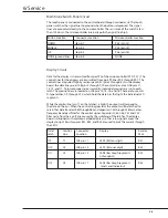
The humidifier board contains all the electronic circuitry involved with the measurement,
control, computation, memory, logic, power management, and decision making
functions of the servo-controlled humidifier. The principal integrated circuit (IC) on
this board is the 87C550 single component, 8-bit microcontroller. The 87C550 has 4
kilobytes of internal programmable read only memory (PROM), 128 bytes of internal
read/write memory (RAM), six channels of 8-bit analog-to-digital conversion (A/D), two
16-bit counters/timers, a seven-source two priority level nested interrupt structure, input/
output (I/O) expansion, and an on-chip oscillator and clock circuits. The I/O ports on the
microcontroller are listed below.
Port No.
Microcontroller Pin
Function
P0.0
39
Audio Prompt Control
P0.1
38
Watchdog Pulse Output
P0.2
37
Solid State Relay Control
P0.3
36
Safety Relay Control
P0.4
35
Dis play Control for Bar Graph (i,j) &
LED Indicators
P0.5
34
Display Control for Bar Graph (a-h)
P0.6
33
Display Control for RH (ones digit)
P0.7
32
Display Control for RH (tens digit)
P1.0
3
RH Signal Input for A/D
P1.1
4
Heater Current Sense Signal for A/D
P1.2
5
Five Volt Line Monitor for A/D
P1.3
6
Sensor Select Input for A/D
P1.4
7
Ground
P1.5
8
Ground
P2.0
21
Data Bus (PA0)
P2.1
22
Data Bus (PA1)
P2.2
23
Data Bus (PA2)
P2.3
24
Data Bus (PA3)
P2.4
25
Data Bus (PA4)
P2.5
26
Data Bus (PA5)
P2.6
27
Data Bus (PA6)
P2.7
28
Data Bus (PA7)
P3.0
10
Microswitch Sense Input
P3.1
11
Sensor Connect Sense Input
P3.2
12
Watchdog Sense Input
P3.4
14
DOWN Switch Sense Input
P3.5
15
ENABLE Switch Sense Input
P3.6
16
UP Switch Sense Input
P3.7
17
Thermostat / Thermal Fuse Sense Input
Summary of Contents for Ohio Care Plus
Page 20: ...2 General Information 2 4 2 4 Notes...
Page 24: ...4 Using the Servo controlled Humidifier 4 2 4 1 Notes...
Page 46: ...6 Service 6 18 6 18...
Page 53: ...8 Schematics 8 1 Figure 8 1 Wiring Diagram Servo controlled Humidifier 8 Schematics CI 18 059...
Page 55: ...8 Schematics 8 3 Figure 8 3 Digital section of the Control Display Board Assembly CI 18 061...
Page 56: ...8 Schematics 8 4 Figure 8 4 Analog section of the Control Display Board Assembly CI 18 062...
Page 58: ...8 Schematics 8 6 Figure 8 6 Display section of the Control Display Board Assembly CI 18 064...
Page 67: ......


