6/Service
6-13 6-13
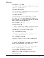
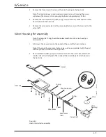
3. Make sure the valve is in the closed position, then compress the spring and secure
the valve housing to the heat sink with the three screws removed in disassembly.
4. To complete re-assembly reverse steps 1 through 6 in disassembly section.
Note: Make sure that the wires are correctly seated in the wire grooves in the gasket.
5. Perform the Electrical safety check and Valve checkout found at the end of this
section and the checkout procedures in section 3.
Humidifier Controller Disassembly/Reassembly
WARNING
Use extreme care while performing calibration and adjustment procedures, or
while working on the servo-controlled humidifier with the power connected. An
electrical shock hazard does exist; be certain to observe all safety precautions.
CAUTION
s
Use the Static Control Work Station (Stock No. 0175-2311-000) to help ensure that
static charges are safely conducted to ground. The Velostat material is conductive.
Do not place electrically powered circuit boards on it.
To replace any humidifier controller components or the humidity sensor follow these
procedures.
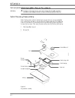
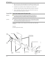
Figure 6-3
Humidifier controller disassembly
Membrane
switch
panel
Display
panel
bezel
Display panel chassis
Control/Display
board assembly
Controller hous-
ing
Mounting bolts
Power
switch
Fuse
Holders
Line
filter
Card guide
CI.18.021
Summary of Contents for Ohio Care Plus
Page 20: ...2 General Information 2 4 2 4 Notes...
Page 24: ...4 Using the Servo controlled Humidifier 4 2 4 1 Notes...
Page 46: ...6 Service 6 18 6 18...
Page 53: ...8 Schematics 8 1 Figure 8 1 Wiring Diagram Servo controlled Humidifier 8 Schematics CI 18 059...
Page 55: ...8 Schematics 8 3 Figure 8 3 Digital section of the Control Display Board Assembly CI 18 061...
Page 56: ...8 Schematics 8 4 Figure 8 4 Analog section of the Control Display Board Assembly CI 18 062...
Page 58: ...8 Schematics 8 6 Figure 8 6 Display section of the Control Display Board Assembly CI 18 064...
Page 67: ......


