6/Service
6-16 6-16
Sensor Calibration
1. Turn on the incubator and set the temperature to 30°C in the manual mode. Allow
temperature to stabilize.
2. Turn on the humidifier and set the humidity to 75%. Allow the humidity to stabilize.
3. Take the cap off the calibration bottle.
Important: In order for the water in the calibration bottle to be completely
saturated, most of the salt should remain undissolved. There should be as little
standing water above the salt line as possible to minimize the response time.
4. Add one half bottle cap distilled water to the bottle to cover the salt.
5. Shake the bottle to thoroughly mix the salt and water solution. Place the elbow on
the bottle. The smaller end goes over the bottle.
Note: The solution in the calibration bottle should be approximately the same
temperature as the incubator's infant chamber. If you used cold water or the
calibration bottle was in a cold environment, place the bottle in the incubator
and allow it to warm before attaching it to the humidity probe. If there is a large
temperature difference between the solution in the bottle and the humidity sensor,
a system fail prompt (E2.5) may sound.
6. Slide the elbow over the humidity sensor (mounted on the inside hood on the back
wall, it is the bottom, shorter probe) until it stops.
7. Wait 30 minutes.
8. Verify the RH display reads 75 ± 2 %. If it does not, perform steps 9, 10 and 11.
If it does, skip to step 12.
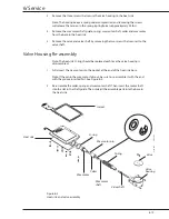
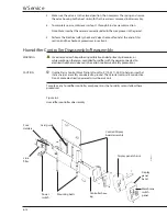
9. Loosen the two bolts at the bottom of the humidifier controller housing that secure
it to the base platform. Lower the controller housing while tilting the bottom of
the housing toward you. This will allow access to adjust the potentiometer on the
Controller/Display Board.
10. Adjust the potentiometer (R30, CALIBRATE) on the control/display board until the
RH display reads 75%.
11. Re-assemble the humidity controller to the incubator base with the two mounting
bolts.
12. Remove the calibration bottle by pulling it straight it off the humidity sensor.
Summary of Contents for Ohio Care Plus
Page 20: ...2 General Information 2 4 2 4 Notes...
Page 24: ...4 Using the Servo controlled Humidifier 4 2 4 1 Notes...
Page 46: ...6 Service 6 18 6 18...
Page 53: ...8 Schematics 8 1 Figure 8 1 Wiring Diagram Servo controlled Humidifier 8 Schematics CI 18 059...
Page 55: ...8 Schematics 8 3 Figure 8 3 Digital section of the Control Display Board Assembly CI 18 061...
Page 56: ...8 Schematics 8 4 Figure 8 4 Analog section of the Control Display Board Assembly CI 18 062...
Page 58: ...8 Schematics 8 6 Figure 8 6 Display section of the Control Display Board Assembly CI 18 064...
Page 67: ......


