6/Service
6-15 6-15
7. Snap the stain relief off the old humidity sensor cable connector so it will fit
through the hole in the base platform in the back of the incubator. Then push the
sensor cable connector out the hole.
8. Pull the old humidity sensor assembly out of the incubator by sliding the cable
through the hole in the hood.
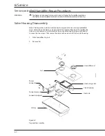
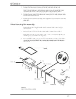
Figure 6-4
Humidity sensor assembly
9. Install the new cable by reversing steps 6 through 8. Use a tie wrap to attach
the sensor cable to the rail cables (this will prevent the sensor cable from being
damaged when the fill tray is inserted). For correct attachment of the sensor
connector strain relief, see Figure A-3 in the Appendix .
10. Route the cable out the rear of the base, through the hole near the air filter, and
around the filter.
11. Replace the filter. Secure the filter cover with the filter mounting knobs. The hole
on the top of the filter cover should line up with the cable.
12. Slide the mounting block, backed by the two shims, over the temperature
compartment probe from the inside of the hood. Align the cable guard on the rear
block with the sensor cable on the outside of the hood. Secure the blocks with the
two Phillips head screws. Refer to Figure 6-4.
13. Anchor the sensor cables to the outer hood with the clip removed earlier.
14. On double walled units, replace the inner walls.
15. Perform the sensor calibration procedure.
Mounting
screw
Mounting
block, rear
Foam gasket
Hood wall
Humidity sen-
sor
Temperature
compartment
probe
Mounting
block, front
Shims
CI.18.005, .007, .010
Register to rear cap, then remove box
Summary of Contents for Ohio Care Plus
Page 20: ...2 General Information 2 4 2 4 Notes...
Page 24: ...4 Using the Servo controlled Humidifier 4 2 4 1 Notes...
Page 46: ...6 Service 6 18 6 18...
Page 53: ...8 Schematics 8 1 Figure 8 1 Wiring Diagram Servo controlled Humidifier 8 Schematics CI 18 059...
Page 55: ...8 Schematics 8 3 Figure 8 3 Digital section of the Control Display Board Assembly CI 18 061...
Page 56: ...8 Schematics 8 4 Figure 8 4 Analog section of the Control Display Board Assembly CI 18 062...
Page 58: ...8 Schematics 8 6 Figure 8 6 Display section of the Control Display Board Assembly CI 18 064...
Page 67: ......


