6/Service
6-4 6-4
The following sections describe, in detail, the functions of each circuit on the printed
circuit board. General design practices were followed to attenuate the EMI/RFI noise.
On all signal lines traveling into or out of the control portion of the printed circuit
board, ferrite bead and capacitors are installed. These devices do not readily affect the
operation of the board and are not discussed in the functional description.
Power Supply
The transformer T1 steps the line voltage down to typically 11V~ under normal load.
In the 120V~ option, the jumpers JP9 and JP10 are installed; in the 230V~ option,
the jumper JP8 is installed. There are fuses F3 and F4 to protect the transformer,
and a fuse F1 to protect the rest of the circuit. The output of the transformer is full-
wave rectified by the bridge rectifier D1, and filtered by capacitors C1 and C2. The
zener diode D11 and resistor R45 supply a stable 9.1 VDC to the circuit. The voltage
regulator U1 provides 5 VDC to the circuit. The capacitor C3 is used to filter the output
voltage and keep the regulator from oscillating.
Microcontroller
The 87C550 microcontroller U4 includes a one-time programmable EPROM. The
crystal speed is 7.3728MHz. This yields a clock frequency of 1.2288MHz, or one
sixth of the crystal frequency. This can be read from the ALE/P line (pin 30) on the
microcontroller. The capacitor C47 ensures that the microcontroller is held in reset until
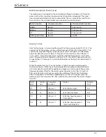
the voltage supply has stabilized. The port designations are located in the table on the
first page.
Humidity Sensor
The HyCal humidity sensor requires an excitation voltage of 5VDC and will produce
a voltage output directly proportional to the percent of relative humidity (0.8V - 3.9V).
The following equation shows this linear relationship.
Vout = 0.8V + (0.031x %RH)
The microcontroller determines the actual connection of the sensor to the printed
circuit board. Pins 1 and 6 are shorted together on the sensor side of connector J3.
The microcontroller senses this short via the P3.1 (pin 11) line. When the sensor is
connected, that line is a low logic level; when the sensor is disconnected, that line is
a high logic level. P3.1 is internally pulled high by the microcontroller.
Humidity Circuit
The signal from the humidity sensor is applied to a voltage follower U3A with very low
input noise and bias current characteristics, because of the high output impedance
of the sensor. This follower has unity gain. The diodes D6 and D7 protect the circuit
and sensor from electrostatic discharge (ESD), while diode D4 protects the circuit and
sensor from over-voltage. The RC network of C25 and R11 provide a low pass filter for
the sensor output signal. Resistor R57 is a pull-up resistor to lift the input signal to 5V if
the sensor is disconnected.
Summary of Contents for Ohio Care Plus
Page 20: ...2 General Information 2 4 2 4 Notes...
Page 24: ...4 Using the Servo controlled Humidifier 4 2 4 1 Notes...
Page 46: ...6 Service 6 18 6 18...
Page 53: ...8 Schematics 8 1 Figure 8 1 Wiring Diagram Servo controlled Humidifier 8 Schematics CI 18 059...
Page 55: ...8 Schematics 8 3 Figure 8 3 Digital section of the Control Display Board Assembly CI 18 061...
Page 56: ...8 Schematics 8 4 Figure 8 4 Analog section of the Control Display Board Assembly CI 18 062...
Page 58: ...8 Schematics 8 6 Figure 8 6 Display section of the Control Display Board Assembly CI 18 064...
Page 67: ......


