EN-
5000 Series Indicators
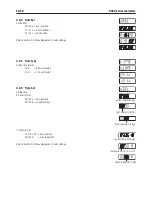
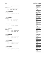
.1.5 Lock Print Button
Set the status.
OFF = Prnt button s unlocked.
ON = Prnt button s locked.
.1. Lock Unit Button
Set the status.
OFF = Unt button s unlocked.
ON = Unt button s locked.
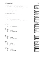
.1. Lock Function Button
Set the status.
OFF = Functon button s unlocked.
ON = Functon button s locked.
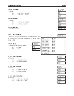
.1. Lock Mode Button
Set the status.
OFF = Mode button s unlocked.
ON = Mode button s locked.
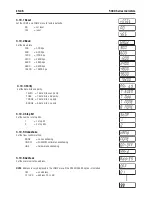
.1. Lock Tare Button
Set the status.
OFF = Tare button s unlocked.
ON = Tare button s locked.
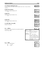
.1.10 Lock Menu Button
Set the status.
OFF = Menu button s unlocked.
ON = Menu button s locked.
NOTE
: When the Menu button s locked, the user may unlock ths button by holdng the Menu button for 10
seconds untl UNLOCK s dsplayed. The hardware Lock Swtch must be n the unlocked poston.
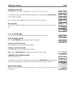
.1.11 End Lock
Advance to the next menu.
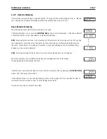
.1 Security Switch
A slde swtch s located on the Man PCB board. When the swtch s set to the ON poston, user menu settngs that were locked
n the Menu Lock and Key Lock menus can be vewed but not changed.
Open the housng as explaned n Secton 2.3.1. Set the poston of securty swtch SW2 to ON as shown n Fgure 1-3.
Summary of Contents for T51P
Page 1: ... 5000 Series Indicators Instruction Manual T51XW Indicator T51P Indicator ...
Page 2: ...ii ...
Page 63: ......


