Installation FlexPak6 & FlexPak6D Enclosures
Chapter 3
OEM6 Family Installation and Operation User Manual Rev 12
50
3.3.6
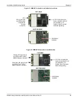
FlexPak6D Status Indicators and Connector Labels
The following figure indicates the connector locations and the table identifies and defines the connectors.
Figure 21: FlexPak6 Connectors
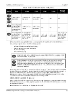
Table 7: FlexPak6D Status Indicators and Connector Labels
Table 8: FlexPak6 and FlexPak6D Default Serial Port Configuration
3.4
Installing NovAtel PC Utilities
The NovAtel PC Utilities application contains complete instructions for the installation and use of the NovAtel
PC utilities.
Connector
Description
Antenna/
Position Valid
Solid
GREEN
with valid position
Solid
RED
indicates a board error
COM1
Flashing
GREEN
when transmitting data from COM1
Flashing
RED
when receiving data on COM1
COM2
Flashing
GREEN
when transmitting data from COM2
Flashing
RED
when receiving data on COM2
Power
Solid
RED
when voltage within the acceptable range is applied
I/O
Input and output port for additional signals such as PPS, Event 1 and 3, VARF, ERROR or
Position Valid
USB Communications port
Model
COM1
COM2
COM3
FlexPak6
RS-232/RS-422
a
a. Mode selected via software commands.
RS-232/RS-422
b
b. Selected via MODE pin on the I/O connector.
Not available
FlexPak6D
RS-232
RS-232/RS-422
b
Not available
COM 2
I/O
COM 1
ANT 1
ANT 2
Antennas
COM1 and COM2
Power
USB
I/O
ANT1
ANT2
Download the latest PC Utilities software including NovAtel Connect™ along with the necessary
user documentation from the PC Software section of

