


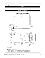
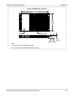

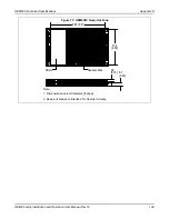


OEM617D Technical Specifications
Appendix C
OEM6 Family Installation and Operation User Manual Rev 12
138
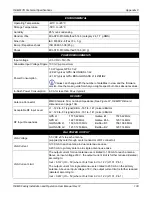
ENVIRONMENTAL
Operating Temperature
-40
C to +85
C
Storage Temperature
-55
C to +95
C
Humidity
95% non-condensing
Random Vibe
MIL-STD-810G Method 514.6 (category 24, 7.7 g RMS)
Sine Vibe
IEC 60068-2-6 (Test Fc - 5 g)
Bump / Repetitive shock
ISO 9022-31-06 (25 g)
Shock
MIL-STD-810G Method 516.6 (40 g)
POWER REQUIREMENTS
Input voltage
+3.3 VDC +5%/-3%
Allowable Input Voltage Ripple 100 mV p-p maximum
Power Consumption
1.9 W typical, GPS L1/L2
<2.0 W typical, GPS+GLONASS L1/L2
<2.1 W typical, GPS+BDS+GLONASS L1/L2/B1/B2
Values can change with the number of satellites in view and the firmware
version. Use them as a guide for what you might expect but not as absolute values.
In-Rush Power Consumption 6.0 A for less than 60
s (typical)
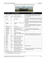
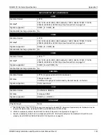
RF INPUT
Antenna Connector
MMCX female, 50
nominal impedance (See
Acceptable RF Input Level
L1: -122 to -87 (signal) dBm, -161 to -141 (noise) dBm/Hz
L2: -126 to -93 (signal) dBm, -161 to -141 (noise) dBm/Hz
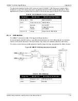
RF Input Frequencies
GPS L1:
1575.42 MHz
GPS L2:
1227.60 MHz
GLONASS L1:
1593-1610 MHz
GLONASS L2:
1237-1253 MHz
Galileo E1:
1575.42 MHz
Galileo E5b:
1207.14 MHz
BeiDou B1:
1561.098 MHz
BeiDou B2:
1207.14 MHz
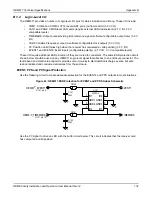
LNA POWER OUTPUT
LNA Voltage
5.0 VDC ±5% to each antenna
(supplied by card through center conductor of RF connector)
LNA Current
0-100 mA to each antenna in dual antenna use case
0-200 mA to primary antenna in single antenna use case
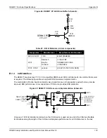
LNA Current Limit
The output current for dual antenna use is limited to 100 mA for each antenna.
Above an input voltage of 6 V, the output current limit is further reduced (derated)
according to:
Iout < 0.1W/ (Vin - 5V) where Vin is from 6 V to 12 V (J1101, Pin 1)
The output current for single antenna use is limited to 200 mA on the primary
antenna. Above an input voltage of 6 V, the output current limit is further reduced
(derated) according to:
Iout < 0.2W/ (Vin - 5V) where Vin is from 6 V to 12 V (J1101, Pin 1)