OEM628 Technical Specifications
Appendix D
OEM6 Family Installation and Operation User Manual Rev 12
156
D.1.2
CMOS Level I/O
The OEM628 provides a number of 2.7 V (3.3 V-compatible) CMOS level I/O pins for status indication and
timing. These I/O include:
•
PPS: Pulse-Per-Second (software configurable to other rates)
•
VARF: Variable Frequency (a software configurable clock output)
•
ERROR: Error indication
•
PV: Position Valid (used to indicate when the receiver has calculated a valid position)
•
EVENT1 and EVENT2: Event inputs (active high by default with configurable polarity)
•
USERIO0 and USERIO1: User GPIO (available through NovAtel’s API)
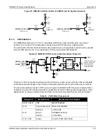
These I/O require additional ESD protection if they are routed to connectors. Some users may require
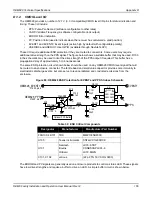
additional drive strength on the PPS signal. The figure below shows a suitable buffer that may be used. R103
in the schematic may be used to limit the drive strength of the PPS output if required. This buffer has a
propagation delay of approximately 5 to 6 nanoseconds.
The same ESD protection circuit shown below should be used on any OEM628 CMOS level signal that will
be routed to an enclosure connector. The ferrite bead and small value capacitor provide some immunity to
electrostatic discharge events, but also serve to reduce radiated and conducted emissions from the
enclosure.
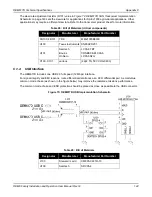
Figure 80: OEM628 ESD Protection for EVENT and PPS Strobes Schematic
Table 32: ESD Critical Components
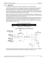
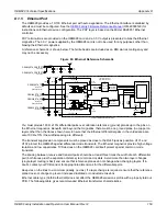
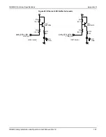
The ERROR and PV signals are generally used on enclosure products to control a status LED. These signals
have low drive strengths and require a buffer to drive an LED. A simple buffer circuit is shown below.
Designator
Manufacturer
Manufacturer Part Number
FFB100, FB101
TDK
MMZ1005B800C
U100
Texas Instruments
SN74LVC1G86DCK
U101
Semtech
Bourns
OnSemi
LC03-6.TBT
CDNBS08-PLC03-6
LC03-6R2G
C101, C102
various
(22 pF 5% 50V COG 0603)
EVENT1
OEM628_EVENT1
PPS
C102
22pF
U100
74LVC1G86
C101
22pF
R103
0
Optional PPS Buffer
P1500, pin 8
OEM628_PPS
P1500, pin 4
FB100
3V3
3V3
3V3
R100 NNP
R102 0
R101 NNP
FB101
U101
PLC03-6
IO1
GND1
GND2
IO2
IO4
GND4
GND3
IO3
1
2
3
4
1
2
4
5
3
8
7
6
5
D
D
D
D
D
D
D
VCC
GND
C100
0.1µF


