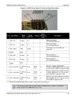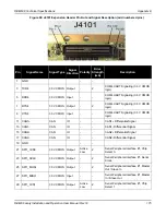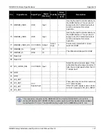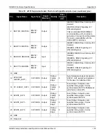
OEM638 Technical Specifications
Appendix E
OEM6 Family Installation and Operation User Manual Rev 12
187
E.1.8
Ethernet Port
The OEM638 provides a 10/100 Ethernet port with auto-negotiation. The Ethernet interface is not enabled by
default and may require configuration (refer to details that follow and consult the
(OM-20000129) for instructions on configuring the Ethernet interface and the
SAVEETHERNETDATA
command.
PHY terminations are provided on the OEM638 card and a 3.3 V output is presented to bias the Ethernet
magnetics. This 3.3 V bias output from the OEM638 card is not to be used for any purpose other than biasing
the Ethernet magnetics.
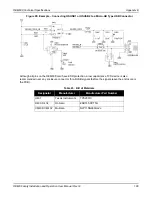
A reference schematic is shown below.
Figure 96: Example - Ethernet Reference Schematic
Care must be taken to provide 100
Ω
±10% differential pairs over unbroken reference (ground) planes up to
the pins on the Ethernet connector.
The Ethernet magnetics (inside the Ethernet jack on the part shown) provide high voltage isolation and
protection components for differential mode transients. ESD protection components must be placed near the
connector pins.
The spacing between receive and transmit pairs should be at least 3-4 times the width of each differential pair
(both traces plus the separation distance) to minimize crosstalk. More than two layer changes should be
avoided (single layer routing is best) and care must be taken to ensure reference planes do not change when
changing layers. If in doubt, contact your PCB vendor for appropriate dimensions for the differential pairs.
Alternately, discrete Ethernet magnetics may be used. Ensure that the Ethernet magnetics selected meet the
specifications in the table below. Ensure the magnetics are no more than 15 cm (6 inches) from the OEM638
expansion connector (the shorter the better). A guide to using discrete magnetics is contained in the OEM628
Technical Reference Section of this manual.


