Version 3.0
23
Navigate
Operator’s Manual
represents the bow of the boat. Icons on the screen are always related
to this object. The two dash lines extending from the bottom of the
screen towards the center of the screen represent your cross-track
error limits. The dotted line extending from the bow of the boat icon
represents your course line. The course line changes direction at the
flags, which represent your waypoints, and continues through to the
end of the active route you entered in
RTE1
. Notice that the cross-
track error lines end at the first flag. As you pass the flag and start
the next leg of your course, these lines will be redrawn to reflect the
course change. Icons that you see left and right of your course are
navigation markers that you define in the Waypoint Bank (
WPT1
)
where a symbol is used as the first character of the waypoint descrip-
tion. The Panorama and Plot screens will automatically place these
navigation markers on the screen as you approach them.
The degree values that you see are your Course Over Ground (COG),
as calculated by the GPS receiver’s position fix to position fix, and
Bearing (BRG) from your present position to the waypoint. The speed
value is your Speed Over Ground (SOG) as calculated by the GPS.
The distance value displayed as the Range (RNG) is calculated from
your present position to the waypoint. The Time-To-Go (TTG) is the
calculated time it will take you to reach the waypoint, based on your
Waypoint Closure Velocity (see
NAV4
description).
To keep the screen from jumping around when you are stopped, the
screen freezes the graphic representation when your speed is under
0.5 Kn in DGPS mode or 2.0 Kn in GPS mode. Once you get under-
way, your course details will update appropriately.
You will see a
RL
or
GC
symbol in the upper right corner of the
display indicating whether you are navigating under Rhumb Line or
Great Circle. This is set in the
CFG
Navigate
menu.
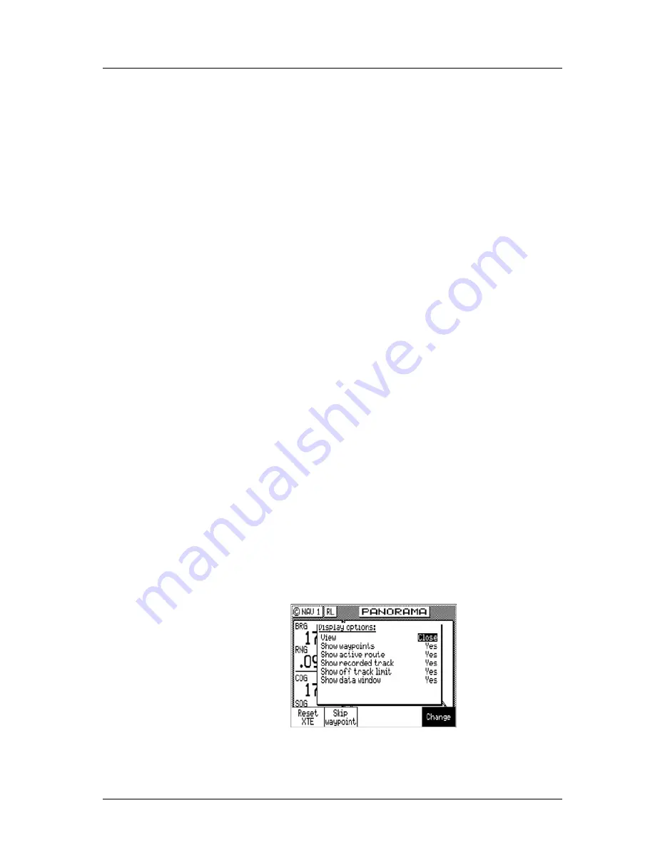
If you press the
EDIT
key, the Panorama Display Option screen will
Summary of Contents for MX500
Page 1: ...oOperator s Installation Manual MX500 Navigation System ...
Page 14: ...Version 3 0 ix Table of Contents Operator s Manual ...
Page 165: ...Version 3 0 151 Configuration Operator s Manual ...
Page 167: ...Version 3 0 153 Datum List Operator s Manual ...
Page 195: ...List of Components Installation Manual Version 3 0 181 APPENDIX F INSTALLATION SECTION ...
Page 196: ...Installation Manual List of Components 182 Version 3 0 SECTION 1 LIST OF COMPONENTS ...
Page 219: ...Installation Notes Version 3 0 205 Installation Manual SECTION 5 INSTALLATION NOTES ...
Page 282: ......
Page 283: ......


