76
Version 3.0
Operator’s Manual
Plot
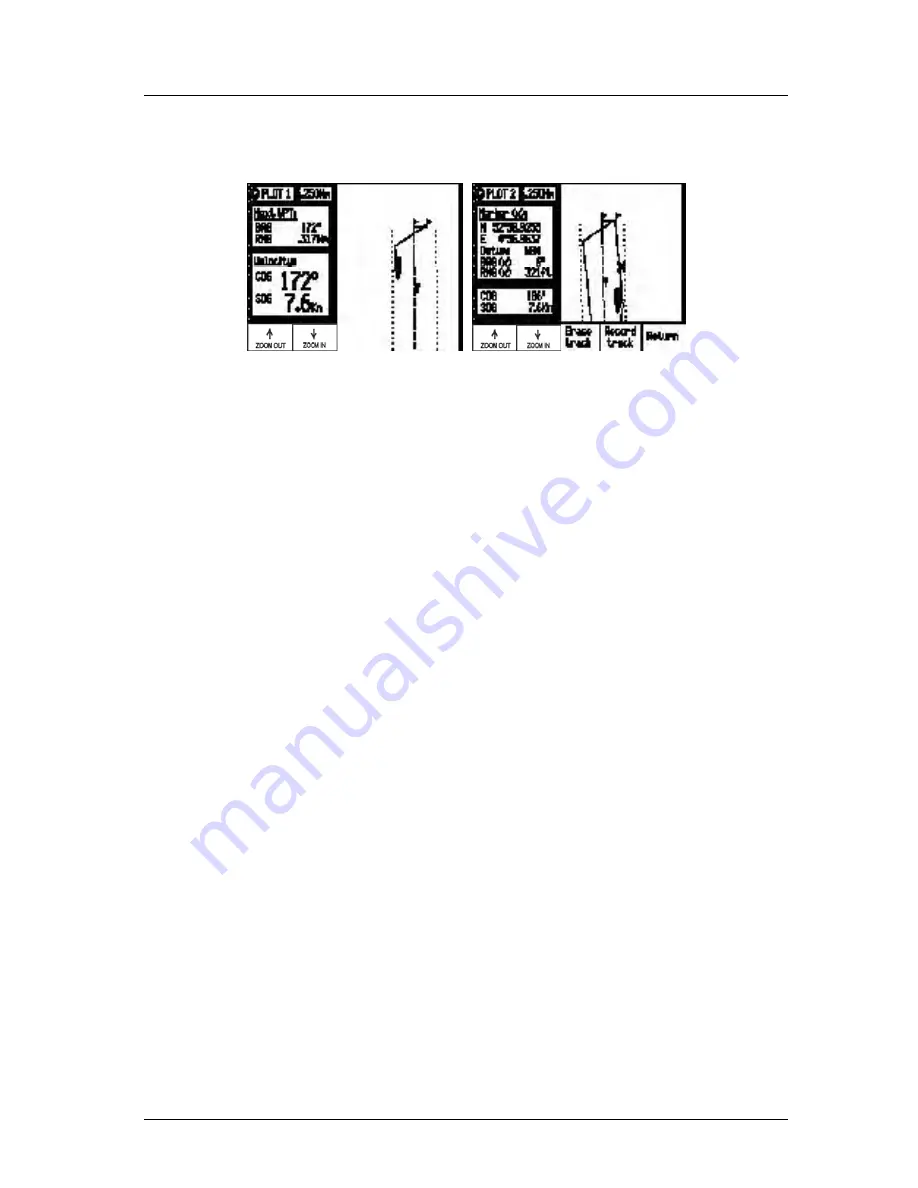
Take a quick look at both screens. They both have a graphical area to
the right, and a text data area to the left.
In the PLOT screens the
UP arrow
key is the
Zoom-out
key; the
DOWN
arrow
key is the
Zoom-In
key. Each time you depress one of
these arrow keys, you scale by one-half or by double the graphical
area. If you look to the top of the screen, just right of the
page num-
ber
(
PLOT 1
or
PLOT 2
), you will see a number in a white square.
This is the scale of the graphic window based on the units selected in
CFG1
Navigation
. Now look along the left and right edge of the
graphic window, you will see some vertical black and white dash
marks (these are harder to see at small scales like 1 and 2 or at large
values such as 64 or 128). Each solid dash mark represents 1 nauti-
cal mile. A broken dash mark indicates 1/100th of a nautical mile
when you are zoomed in at low scale. You will find your bearing and
range to the next waypoint (
PLOT1
) or marker position (
PLOT2
)
just below the page number. The PLOT2 screen also provides the
marker coordinates and the datum currently in use (set in
CFG1
Datum
).
The
CFG1
Navigation
menu allows you to display fractions of the
major unit (nautical miles, statute miles, or kilometers) ranges less
than 1000 in alternate units of feet or meters.
Summary of Contents for MX500
Page 1: ...oOperator s Installation Manual MX500 Navigation System ...
Page 14: ...Version 3 0 ix Table of Contents Operator s Manual ...
Page 165: ...Version 3 0 151 Configuration Operator s Manual ...
Page 167: ...Version 3 0 153 Datum List Operator s Manual ...
Page 195: ...List of Components Installation Manual Version 3 0 181 APPENDIX F INSTALLATION SECTION ...
Page 196: ...Installation Manual List of Components 182 Version 3 0 SECTION 1 LIST OF COMPONENTS ...
Page 219: ...Installation Notes Version 3 0 205 Installation Manual SECTION 5 INSTALLATION NOTES ...
Page 282: ......
Page 283: ......


