58
EN
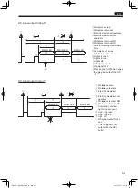
Example 3: Input the workpiece signal
CAUTION
z
z
A 2-wire sensor cannot be used.
A 2-wire sensor has a flow of fine current even while OFF, and could cause a malfunction.
z
z
For the sensor, use a PNP output type 3-wire sensor.
z
z
Depending on the sensor installation environment, a malfunction could occur due to noise.
Make sure to take sufficient noise measures such as setting up grounding. For details, read the instruction
manual of the sensor to be used.
When connecting three or more tools, the setting for the first screwdriver is different but the setting for the second and
subsequent tools is the same as Example 2 and the operation is also the same as Example 2.
1
Connect an external power supply to electric screwdriver 1 and 2
2
Connect the reset switch in such a way that the reset signal is commonly input to electric
screwdrivers 1 and 2
3
Connect the workpiece detection sensor to the workpiece signal of electric screwdriver 1
4
Connect LINK-OUT of electric screwdriver 2 to LINK-IN of electric screwdriver 1
5
Set the following functions
Function
No.
Function
Electric screwdriver 1
Electric screwdriver 2
1
Workpiece
signal
1: Input
1: Input
5
OK signal
output
timing
0: When the set count ends
* For five tools, electric screwdrivers 1 to
4 are “0”
0: When the set count ends
or
1: When the set count ends and the
workpiece is removed
* For five tools, only electric screwdriver 5
can be selected
Electric screwdriver 1
Electric screwdriver 2
Signal
+24 V
Workpiece
Reset
LINK-
IN
OK
0 V
+24 V
Workpiece
Reset
LINK-
OUT
0 V
Wiring
color
Red
White
Green
Yellow
Brown
Black
Red
White
Green
Gray
Black
Pin No.
1
2
3
4
5
12
1
2
3
7
12
Connection
example
㻗 㻙
External power supply
Reset switch
I/O direction
TV07521-1_DLV30S12P-AYK_en.indb 58
2017/02/10 15:56:38


