background image

33

EN

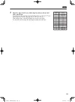
Adjust the upper limit of screw fastening time value and lower limit 

value, respectively

For example, set the upper limit of screw fastening time to +10% (ex: 0.77 sec.) 

and the lower limit of screw fastening time to -10% (ex. 0.54 sec.).

When setting values, consider tolerances such as the screw length.

It is smooth to set the values after deciding the rotation time and level.

Motion 

No.

Setting

1

Optional

2

L1

3

10

4

L9

5

30

6

L1

7

54

8

77

9

0

10

Optional

11

Optional

TV07521-1_DLV30S12P-AYK_en.indb   33

2017/02/10   15:56:35

Summary of Contents for delvo DLV30S AY Series

Page 1: ...I CO LTD 9 4 NAKAIKEGAMI 2 CHOME OHTA KU TOKYO 146 8555 JAPAN Tel 81 3 3755 1111 Fax 81 3 3753 8791 EN This instruction manual is written in English Instruction manuals in other languages can be downl...

Page 2: ...23 9 Motion Setting 24 Switching the motion setting mode 24 Initializing the motion setting 24 Setting the screw count 25 Setting the speed level and time 26 Setting auto reverse mode 28 10 Measuring...

Page 3: ...n twice extra tightening Also it cannot be used for screw tightening of such things as wood or drywall Depending on fastening conditions screws may become loose Improper impacts could decrease product...

Page 4: ...nsult with the store where you purchased the product Package content and list of accessories DLV30S series DLV45S series DLV70S series Package content and accessories Quantity Package content and acce...

Page 5: ...Handle exterior resin part of main unit b Changeover Switch c Torque Scale standard d Torque Adjustment Ring Model Rubber Ring Torque adjustment ring cover Lever start type Push start type Color Mate...

Page 6: ...cause a failure 1 2 3 4 5 6 7 8 1 Main LED Various operations and settings are notified by lighting flashing and color 2 Parameter LED Displays the screw count or set value 3 UP button Increases the s...

Page 7: ...r reference Metric Thread mm 2 6 to 5 0 Inch Thread 3 to 10 Tapping Screw mm 2 5 to 4 0 Bit Type NK35 HEX 6 35mm 1 4 Mass kg lbs 0 71 1 56 Input Voltage 40 V DC Dedicated Power Supply DEA0151N AZ or D...

Page 8: ...age Operating Environment less than 2000 m above sea level Pollution Degree According to IEC60664 1 Pollution Degree 2 Over Voltage Category According to IEC60664 1 Over Voltage Category I 1 LPA A wei...

Page 9: ...f use of speed level and output torque for reference CAUTION z z Range of use of speed level and output torque is for reference The range of use changes depending on the fastening conditions workpiece...

Page 10: ...ool mechanical loss and grease conditions It could vary depending on differences in the tool itself z z When the speed is changed the motor sound changes This is not an error Free Speed min 1 Free Spe...

Page 11: ...re the bit does not come off To remove the bit pull out the bit while pulling the sleeve Attaching the suspension bail CAUTION z z If the suspension bail is pulled forcefully it may not return to orig...

Page 12: ...o clicking sound z z Recommended grease separately sold Idemitsu Kosan Co Ltd Daphne Eponex SR No 2 Showa Shell Sekiyu K K Alvania Grease S2 Cosmo Oil Co Ltd DYNAMAX No 2 1 Turn the torque adjustment...

Page 13: ...the semicircle rib of the frame handle 2 Attach the parts to the positions shown in the following figure 3 Match the rib of the Pistol Grip body B and the groove of the frame handle Match the semicir...

Page 14: ...commercially available fixing jig CAUTION z z Do not block the hole on the frame handle as doing so could cause a failure due to heating Fixing position of fixing jig Hole TV07521 1_DLV30S12P AYK_en i...

Page 15: ...e the electric screwdriver Also when the tool is used for a long time the rotation part of the electric screwdriver becomes worn and the ability to remove static electricity decreases Periodically req...

Page 16: ...hile the tool is rotating Doing so could cause a failure z z When the tool is not used set the switch to neutral position z z Do not apply a shock such as dropping or excessive load to the changeover...

Page 17: ...rt switch to start Releasing the start switch stops rotation Lever start type When you press the lever switch the bit rotates Releasing the lever switch stops rotation For the lever start type the lev...

Page 18: ...he main LED lights in green a buzzer sounds and the screw count on the parameter LED changes by one Increase decrease of the screw count changes in accordance with the setting When screw tightening is...

Page 19: ...standard The output torque range is not guaranteed 1 Turn the torque adjustment ring cover counterclockwise to remove it 2 To increase the output torque turn the torque adjustment ring clockwise To de...

Page 20: ...ay be initialized at the time of repair in order to check operation Please note that there is no function to output the set values to an outside device In screw fastening mode press and hold the MEMOR...

Page 21: ...hen the set count ends and the workpiece is removed 0 p 52 6 NG signal output time 0 sec OFF 0 1 9 9 sec 0 1 sec intervals 0 1 p 36 7 NG display 0 Do not continue 1 Continue 0 p 36 8 NG signal output...

Page 22: ...que reached the set torque and rotation stopped during reverse turning E5 In auto reverse mode setting rotation stopped when the start switch is released during reverse turning E6 In auto reverse mode...

Page 23: ...settings return to the default For each motion setting channel it is possible to use the function setting for initialization If you do not remember settings we recommend that the settings be initializ...

Page 24: ...e buzzer sounds the main LED lights in red and the workpiece LED goes OFF The currently set channel No between C1 and C8 is displayed on the parameter LED Press and hold Channel No Lights off Lights i...

Page 25: ...ral side 2 Press the start switch Lever start type Push start type While pressing the start switch the channel No and set value are displayed in order on the parameter LED Displays Channel No Motion N...

Page 26: ...DOWN button to select a set value To check the set motion No press the MEMORY button p 18 3 Press the SELECT button to select the next motion 4 Press and hold the MEMORY button to save the setting Th...

Page 27: ...lights in purple and the workpiece LED goes OFF The mode enters motion setting mode 2 Use the UP button or DOWN button to set the screw count 1 to 99 Pressing and holding the button increases the coun...

Page 28: ...ening time 0 9 9 sec 3 Use the UP button or DOWN button to set a value 4 Press and hold the MEMORY button to save the setting Timing chart When rotation stops before the lower limit of screw fastening...

Page 29: ...e setting once 1 2 3 6 4 5 Speed Time 1 Start or middle 2 Finish 3 Rotation time at start or middle 4 Lower limit of screw fastening time 5 Upper limit of screw fastening time 6 OK range Set either th...

Page 30: ...t be transmitted to the bit Set this item after checking the actual rotation status 1 Setting the speed level and time p 26 2 In screw fastening mode press and hold the MEMORY button and the UP button...

Page 31: ...10 Reverse speed level Optional Optional Optional 11 Reverse rotation time Optional Optional 0 sec Reverse after torque up 1 2 3 4 5 6 7 a 0 8 9 b c Speed Time 1 Middle 2 Reverse rotation 3 Finish 4...

Page 32: ...er limit of screw fastening time 1 2 3 4 7 5 6 Speed Time 1 Middle 2 Finish 3 Start 4 Stop 5 Rotation time at start 6 Rotation time at middle 7 Lower limit of screw fastening time TV07521 1_DLV30S12P...

Page 33: ...value respectively While pressing the button a value is displayed When SELECT button is pressed the previous measurement result is canceled The duration of measurement is from when the electric screw...

Page 34: ...ue Example 0 50 sec Press and hold the SELECT button to cancel the measurement result The mode is switched to the motion setting mode 3 Based on the measured minimum value set the rotation time at sta...

Page 35: ...x 0 77 sec and the lower limit of screw fastening time to 10 ex 0 54 sec When setting values consider tolerances such as the screw length It is smooth to set the values after deciding the rotation tim...

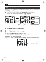
Page 36: ...f Lights in purple Function No Set value The mode enters function setting mode 2 Press the SELECT button to select the function No 3 Use the UP or DOWN button to select a set value 4 Press the SELECT...

Page 37: ...g mode 2 Press the SELECT button to select function No 4 3 Use the UP button or DOWN button to change the screw fastening confirmation time 0 9 9 sec 4 Press the SELECT button to select function No 5...

Page 38: ...between E1 and E9 The main LED goes off At this point if you press the UP button the mode changes to screw fastening mode Only with E7 regardless of the set value the NG signal is output until the wo...

Page 39: ...ew fastening mode automatically When NG display is set to 1 Continue 1 2 3 4 5 6 7 7 0 8 9 a b MAIN LED MAIN LED 1 NG occurs 2 Press the UP button 3 NG signal output time 4 NG display continues 5 Ligh...

Page 40: ...ount during work 1 In screw fastening mode press and hold the SELECT button Press and hold The screw count returns to the initial set value Reset is possible during the screw fastening confirmation ti...

Page 41: ...button to save the setting 5 Slide the changeover switch to the L side 6 Press the DOWN button The buzzer sounds the LED lights in blue and the workpiece LED goes off Lights in blue Press Lights off...

Page 42: ...vantages Advantages Disadvantages You can rotate the screw little by little Break hold time of 0 2 sec occurs Prevents screw tightening relying on familiarity or instinct of workers Prevent screw tigh...

Page 43: ...d the keys are unlocked While keys are locked the following functions are valid z z Count return function z z Data receiving mode z z UP button during screw fastening confirmation time z z UP button d...

Page 44: ...be set from the remote controller For details on the remote controller see Separately sold products p 65 Switching data receiving mode 1 In screw fastening mode press and hold the MEMORY button and D...

Page 45: ...hes in blue and the mode returns to screw fastening mode Receiving Received successfully Lights in blue Flashes in blue When reception fails the main LED lights in yellow again to wait for data recept...

Page 46: ...Reset signal Input 4 Yellow LINK IN Input Forced stop signal 5 Brown OK signal Output 6 Blue NG signal Output 7 Gray LINK OUT Output Channel switching signal 8 Orange Torque up count signal Output 9...

Page 47: ...Insert External signal specifications I O circuit CAUTION z z There is no internal power supply Supply power 24 VDC from outside Electric screwdriver internal circuit Input signal Load Input circuit...

Page 48: ...z For connection use thick wire as much as possible AWG20 or more is recommended z z For connection of an external signal use a commercially available terminal block z z A 2 wire sensor cannot be use...

Page 49: ...l power supply Signal cable Input signal External power supply External wiring when a 3 wire sensor is used Photoelectric proximity sensor etc Connection example of output signal Signal cable Output s...

Page 50: ...ignal is ON Channel A B C ON OFF While the input signal is ON channel A B C is ON Output signal Signal timing Remarks OK signal ON OFF When the OK signal is output ON for 0 1 sec Or ON until the workp...

Page 51: ...ing For details read the instruction manual of the sensor to be used By using the workpiece signal it is possible to prevent human errors and improve work quality 1 Turn off the power of the electric...

Page 52: ...completing a series of tightening before the screw count reaches the set value NG occurs and the parameter LED displays E7 Set workpiece again or input the reset signal If workpiece is removed after...

Page 53: ...kpiece NG starts NG E7 in case workpiece is removed half way through 1 Press and hold the MEMORY button and SELECT button The mode enters function setting mode 2 Press the SELECT button to select func...

Page 54: ...Setting Details 0 When the set count ends Set count ends Screw fastening confirmation time OK signal output Remove workpiece OK signal output OFF By pressing the UP button during the screw fastening...

Page 55: ...off b OK signal output c OK signal OFF d Pressing the UP button skips the step and outputs the OK signal OK signal output timing 1 1 2 3 4 5 6 7 8 9 b 0 a MAIN LED MAIN LED MAIN LED 1 Workpiece setup...

Page 56: ...eration If a problem occurs on the workpiece during screw tightening and the workpiece needs to be removed you can reset the series of operations CAUTION z z Make sure to connect an external power sup...

Page 57: ...n order of connection and when the set screw count is reached the next connected electric screwdriver becomes operable One electric screwdriver is operated at a time Two or more screwdrivers cannot be...

Page 58: ...externally connected reset switch for 0 5 seconds 1 Connect an external power supply to electric screwdriver 1 and 2 2 Connect the reset switch in such a way that the reset signal is commonly input to...

Page 59: ...e signal of electric screwdriver 2 Connect the electric screwdrivers 2 and 3 in the same way 4 Connect LINK OUT of electric screwdriver 3 to LINK IN of electric screwdrivers 1 and 2 5 Set the function...

Page 60: ...y that the reset signal is commonly input to electric screwdrivers 1 and 2 3 Connect the workpiece detection sensor to the workpiece signal of electric screwdriver 1 4 Connect LINK OUT of electric scr...

Page 61: ...o control operation without turning off the electric screwdriver You can add conditions by combining workpiece signals for example place workpiece workpiece signal ON forced stop signal ON remove work...

Page 62: ...ow green Black Pin No 1 9 10 11 12 Connection example External power supply Switch etc I O direction 1 Press and hold the MEMORY button and SELECT button The mode enters function setting mode 2 Press...

Page 63: ...es of the external signal input and output properly connected Are electronic parts to be used properly connected Check the wiring Also carefully read the instruction manual of the electronic parts to...

Page 64: ...heck the screw fastening conditions and set the output torque and rotation level Depending on the material torque may not be transmitted if a screw is tightened at high speed Is the area surrounding t...

Page 65: ...ne parts CAUTION z z For repair or part replacement ask your dealer Repair requires special knowledge and skills If repair is performed at a place other than a specialty store the tool may not demonst...

Page 66: ...torque z z Use a combination of Nitto Kohki s measuring devices to measure the output torque z z If the output torque value has decreased turn the torque adjustment ring to adjust the torque Screw fa...

Page 67: ...Z z z 100 VAC 240 VAC z z Maximum Rated Power 240W z z Compatible models All models described in this document Signal cable DLW9090 External signal connection cable z z Cable length 3 m z z Terminal p...

Page 68: ...ont view DLV45S06P AY DLV45S12P AY DLV70S06P AY Side view Common to DLV45S Common to DLV70S 46 5 1 8 46 5 1 8 39 5 DIA 1 56 39 5 DIA 1 56 6 5 0 26 6 5 0 26 4 5 0 18 4 5 0 18 4 5 0 18 4 5 0 18 39 5 1 5...

Page 69: ...ut to the electric screwdriver K Keylock Locks button operations L Lever start type The start method with which the tool rotates by pressing the lever Link function Link connection Function that links...

Page 70: ...nd The sound issued when screw tightening is completed as set each time a screw is tightened Speed level A standard speed Lv1 is the minimum speed and Lv9 is the maximum speed Start timing of workpiec...

Page 71: ...display 20 NG signal output 54 NG signal output time 36 O Operation mode 18 Output torque 7 17 P Parameter LED 4 Pistol Grip 2 11 65 Power supply 65 Push start type 15 R Remote controller 42 65 Reset...

Page 72: ...1 sec intervals 0 5 OK signal output timing 0 When the set count ends 1 When the set count ends and the workpiece is removed 0 6 NG signal output time 0 sec OFF 0 1 9 9 sec 0 1 sec intervals 0 1 7 NG...

Page 73: ...TV07521 1_DLV30S12P AYK_en indb 71 2017 02 10 15 56 39...

Page 74: ...TV07521 1_DLV30S12P AYK_en indb 72 2017 02 10 15 56 39...

Page 75: ...TV07521 1_DLV30S12P AYK_en indb 3 2017 02 10 15 56 39...

Page 76: ...564 Tel 65 6227 5360 Fax 65 6227 0192 NITTO KOHKI CO LTD Bangkok Representative Office M A Business Center Q House Convent Bldg 38 Convent Rd Silom Bangrak Bangkok 10500 Thailand Tel 66 2632 0307 Fax...

Reviews: