Drive parameters Communications
50
Commander S100 User Guide
Making the drive run can be a single-step or two-step process. If an enable signal is configured as a function of a digital input, the drive display will
show inh (inhibit) and the enable signal needs to be active before the drive is able to run or jog. If an enable is not configured, the drive display will
show rdy (ready) and the drive will run when any run or jog signal is provided.
The direction can be controlled either by the type of run or jog signal supplied or by the direction input. The direction input is not able to override an
explicit signal such as Run Forward (2).
Run/Stop Configuration
(P0.10) can be used to quickly configure the control inputs that allow the motor to run to match an application and local wiring
regulations.
Run/Stop Configuration
(P0.10) changes the functions of T12 Digital Input 2, T13 Digital Input 3, T14 Digital Input 4 and the Keypad Run and Stop
buttons. The changes to the control connections and details on running and stopping the drive in each configuration can be found below.
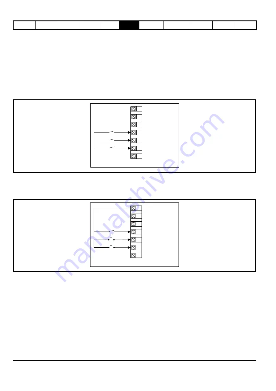
P0.10 = Enable, Run Forward & Run Reverse (1) Default
The drive will not be able to run without an active Enable signal on digital input 2. Run the drive using a Run Forward signal on digital input 3 or a Run
Reverse signal on digital input 4.
If both Run Forward and Run Reverse signals are active at the same time, the drive will decelerate to 0 Hz (STOP) until one signal is removed.
P0.10 =
Run Forward & Run Reverse (3-Wire
) (2)
When a Run Permit signal is active, a Run signal (Run Forward or Run Reverse) will latch and remain active until the Run Permit becomes inactive,
even if the Run signal itself is removed. This allows for a momentary switch or a button to be used to provide the run signals. If the drive is running
forward and a Run Reverse is triggered, the drive will decelerate to 0 Hz using the selected deceleration rate then immediately accelerate to the
inverse of the reference using the selected acceleration rate.
9
10
11
12
13
14
15
+24 V Output
0 V
DIO 1
Enable (DI 2)
DI 5
Enable and RF/RR Signals (P6.13 = 1)
Run forward (DI 3)
Run reverse (DI 4)
9
10
11
12
13
14
15
+24 V Output
0 V
DIO 1
Run Permit (DI 2)
DI 5
RF/RR 3 Wire Control (P6.13 = 2)
Run forward (DI 3)
Run reverse (DI 4)
Summary of Contents for COMMANDER S100
Page 118: ...0478 0650 02...


