4.33
EDH0162En1040 – 06/99
MM4005
Motion Control Tutorial
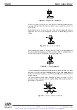
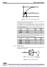
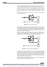
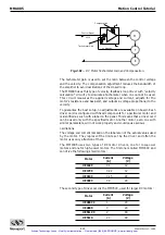
Fig. 4.51
— DC Motor Tachometer Gain and Compensation.
The tachometer gain is used to set the ratio between the control voltage
and the velocity. The compensation adjustment reduces the bandwidth of
the amplifier to avoid oscillations of the closed loop.
The MM4005 uses this type of velocity feedback loop driver with “velocity
calculation” circuitry to simulate a tachometer when one cannot be used.
This circuit measures the applied voltage and current, adjusts for the
motor’s resistance and back-emf, and outputs a voltage proportional to the
velocity.
To guarantee the best setup, no adjustments are available on board. Each
driver card is configured with fixed components for a particular motor and
is identified as such with a label on the panel. This means that a driver card
can be used only with the specified motor. Another motor, even one with
similar parameters, will not work properly and could cause serious
oscillations.
The voltage and current marked on the label are not the actual values used
by the motor. They represent the limits set by the driver and often the
motor uses only a fraction of them.
The MM4005 uses two types of DC motor drivers, one for low-power
motors and one for high-power motors. The first one is called MM16CC and
can drive the following small motors:
Motor
Current
Voltage
(A)
(V)
UE16CC
0.1
12
UE17CC
0.22
12
UE31CC
0.15
24
UE33CC
0.3
24
The second type of driver card is the MM78CC, used for larger DC motors:
Motor
Current
Voltage
(A)
(V)
UE404CC
1
24
UE404S
3
24
UE511CC
2
48
UE511S
2.7
48
M
T
E
V = Velocity
Control Signal
±
10 V
Tachometer Gain
Compensation
Artisan Technology Group - Quality Instrumentation ... Guaranteed | (888) 88-SOURCE | www.artisantg.com

