6-20 Firmware User Guide
IP Address Pools
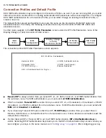
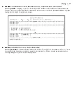
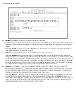
The IP Address Pools screen allows you to configure a separate IP address ser ving pool for each of up to eight
configured Ethernet IP subnets:
This screen consists of between two and eight rows of four columns each. There are exactly as many rows as
there are Ethernet IP subnets configured on the IP Subnets screen.
■
The
Subnet (# host addrs)
column is non-selectable and non-editable. It indicates the network address of
the Ethernet IP subnet for which an address pool is being configured and the number of host addresses
available on the subnet. The network address is equal to the router’s IP address on the subnet
bitwise-ANDed with the subnet mask. The host address count is equal to the subnet size minus three,
since one address is reser ved for the network address, one for the subnet broadcast address, and one for
the router’s inter face address on the subnet.
You can edit the remaining columns in each row.
■
The
1st Client Addr
and
Clients
columns allow you to specify the base and extent of the address ser ving
pool for a par ticular subnet. Entering 0.0.0.0 for the first client address or 0 for the number of clients
indicates that no addresses will be ser ved from the corresponding Ethernet IP subnet.
■
The Client Gateway column allows you to specify the default gateway address that will be provided to
clients ser ved an address from the corresponding pool. The value defaults to the Router’s IP address on
the corresponding subnet (or the Router’s default gateway, if that gateway is located on the subnet in
question). You can override the value by entering any address that is par t of the subnet.
DHCP, BootP, and dynamic WAN clients may receive an address from any one of the address ser ving pools
configured on this screen.
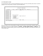
IP Address Pools
Subnet (# host addrs) 1st Client Addr Clients Client Gateway
--------------------- --------------- ------- --------------
192.128.117.0 (253) 192.128.117.196 16 192.128.117.162
192.129.117.0 (253) 192.129.117.110 8 192.129.117.4
Summary of Contents for 4000 Series
Page 10: ...x Firmware User Guide Packet header types B 14 Appendix C Binary Conversion Table C 1 Index ...
Page 18: ...1 8 Firmware User Guide ...
Page 66: ...2 48 Firmware User Guide ...
Page 102: ...3 36 Firmware User Guide ...
Page 130: ...4 28 Firmware User Guide ...
Page 206: ...7 18 Firmware User Guide ...
Page 224: ...9 14 Firmware User Guide ...
Page 274: ...10 50 Firmware User Guide ...
Page 314: ...Index 6 ...

