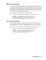
Dummy Logical Disk
If there are no logical disks, the OS is unable to recognize a disk array unit. To avoid
this problem, logical disk 0 of RAID0 (with a single disk drive) is automatically created
when the disk array unit is powered on with all logical disks unbound.
Do not use the created logical disk as it is. After the OS recognizes the logical disk, be
sure to unbind it by using the management software (NEC Storage Manager), and then
bind it.
If the cross call feature is set to OFF, the controller on slave side is unable to recognize
a dummy logical disk. To unbind a dummy logical disk from the controller on slave
side, use the controller that can recognize a dummy logical disk to set the cross call
feature to ON temporarily, then assign a logical disk.
Hot Spare Feature
Spare disks can be installed in the disk array unit. If a disk drive in the same FC loop as
the spare disk fails, the data in the defective disk drive can be regenerated to the spare
disk. After the data recovery, the disk array unit operates normally if another disk drive
is defected. Since the unit also supports the hot-swapping function, the failed disk can
be replaced while the power is on (except for RAID level 0).
To use the hot spare feature, an optional disk drive must be installed.
The figure below shows an example of hot spare operation.
DRV14
Spare disk
DRV14
DRV14
Spare disk
DRV13
DRV13
DRV13
DRV12
DRV12
DRV12
DRV11
DRV11
DRV11
DRV10
DRV10
DRV10
DRV9
DRV9
DRV9
DRV8
→
DRV8
→
DRV8
DRV7
DRV7
DRV7
DRV6
DRV6
DRV6
DRV5
DRV5
DRV5
DRV4
DRV4
DRV4
DRV3
DRV3
DRV3
DRV2
LDN0 RAID5
DRV2
LDN0 RAID5 DRV2
LDN0 RAID5
DRV1
DRV1
DRV1
DRV0
DRV0
DRV0
Failure in DRV1
Recovery of data
in spare disk
Replacement of DRV 1
Data are restored from spare
disk to DRV 1
* DRV:
Disk
drive
LDN: Logical Disk Number
Figure 1-10 Hot Spare Operation
1-18 System
Overview
Summary of Contents for VERSA S1300 Series
Page 1: ... U s e r s G u i d e NEC Storage S1300 ...
Page 2: ......
Page 4: ......
Page 8: ...vi Contents ...
Page 18: ...xvi Using This Guide ...
Page 19: ...1 System Overview Overview System Chassis System Features ...
Page 54: ...A B Figure 2 3 Installing the Rack Mounting Kit 2 6 Setting Up the System ...
Page 73: ...3 Upgrading the System Overview Adding Hard Disk Drives Adding Disk Enclosures ...
Page 86: ...3 14 Upgrading the System ...
Page 114: ...A 8 Appendix ...
Page 117: ...xx ...
Page 118: ... ...

