Section 2: PCB Installation and Startup
Aspila EX Hardware Manual
Section 2: PCB Installation and Startup
2-47
2
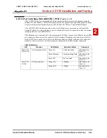
VoIP (VOIPDB) Daughter Board
(Figure 2-20 - Figure 2-21)
The VOIPDB daughter board provides:
•
16 channels
•
Connector for the 16VOIPU PCB (com-
bination provides a maximum of 32 chan-
nels per slot)
The VOIPDB is installed on the 16VOIPU
PCB with a maximum of 6 daughter boards per
system, providing 192 channels (when combin-
ing the 16VOIPU and VOIPDB).
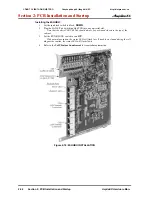
Installing an VOIPDB Daughter Board:
1. Included with the VOIPDB are four
plastic spacers. These are installed in
each of the four corners of the daugh-
ter board. Make sure to attach the
spacers on the front of the daughter
board so when installed, the compo-
nents are facing the 16VOIPU PCB.
2. Position the VOIPDB’S CN6 connector over the CN12 connector on the 16VOIPU PCB. The
CN5 connector on the VOIPDB should then be over the CN11 connector on the 16VOIPU
PCB. Press the boards together, ensuring the plastic spacers lock in place.
3. Install the 16VOIPU PCB into the slot.
Note that the white PCB Pull Tab should always be positioned closest to the top of the
cabinet.
Figure 2-21: INSTALLING THE VOIPDB
4. Set the 16VOIPU’s run/block switch to run,
UP
.
5. The 16VOIPU PCB with the VOIPDB installed will use the first block of 32 trunk ports avail-
able. Confirm the ports used with Program 10-03.
6. Refer to
VoIP Feature Supplement
for required programming.
Figure 2-20: VOIPDB
CÔNG TY VIỄN THÔNG VIỆT PRO
Chuyên phân phối tổng đài NEC
http://vietpro.com.vn


