Section 4: Optional Equipment
4-26
Section 4: Optional Equipment
Aspila EX Hardware
APA and APR Adapters
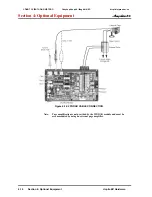
(Figure 4-27 - Figure 4-28)
The APA and APR Adapters provide an analogue interface for the system phone. The APR Adapter
provides ringing which allows the connected device to be used for incoming and outgoing calls. The
APA Adapter does not provide ringing, so the connected device is used for outgoing calls only (for
example, when using a modem). One system phone can have either an APA or an APR Adapter. Both
adapters
cannot
be installed on the same system phone as only one voice path is provided by the sys-
tem phone for the adapters. When installing the APR Adapter, an AC-R AC/DC adapter is required for
power. The maximum distance between the APA or APR Adapter and the analogue terminal is 15
metres.
The APA and APR Adaptors have an RJ11 socket for connection of the single line analogue device.
connection to a suitable Master type line jack unit may be required for some analogue devices.
Neither the APA or APR Adapter supports reverse-polarity, message waiting lamping, or Caller ID.
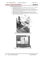
Installing the APA or APR Adapter:
1. Unplug the line cord from the system phone.
2. If only one adapter is to be installed on the phone, the adapter should be installed on the right-
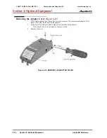
hand side of the phone (beneath the handset). Using a flat-head screwdriver, remove the plas-
tic punch-out piece covering the connector.
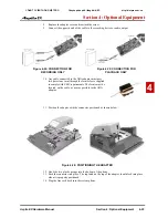
3. Set the dip switches on the APA/APR adapter to the required position.
•
The SW3 switch is used to set the terminating impedance. Setting to position “1” is for a
pure resistance of 600 ohms; position “2” is used for complex impedance (factory setting is
set to “1”).
•
The SW1 switch should be left at its factory setting of “1”. This also applies to the DSW
settings (1 and 5 = on; 2-4, 6-8 = off).
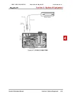
Figure 4-27: RECORDING DIP SWITCH SETTINGS
CÔNG TY VIỄN THÔNG VIỆT PRO
Chuyên phân phối tổng đài NEC
http://vietpro.com.vn

