Section 4: Optional Equipment
4-4
Section 4: Optional Equipment
Aspila EX Hardware
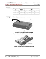
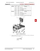
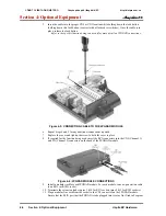
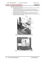
5. Insert the cable into the proper CN4 or CN5 location while holding down the lock button
(holding down this lock button is easiest with a flat-head screwdriver). Once the cable is in
place, release the lock button.
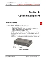
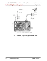
Refer to the specific function being connected for more detail on 2PGDAD connections.
Figure 4-5: CONNECTING CABLE TO THE 2PGDAD MODULE
6. Repeat Steps 4 and 5 for any additional connections required.
7. Replace the cover and tighten the screw to hold the cover in place.
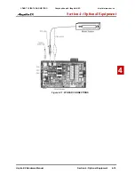
8. If required for the function being used, insert the RCA connectors into the CN3 (Channel 1)
and CN (Channel 2) connectors on the back of the 2PGDAD module.
Figure 4-6: 2PGDAD MODULE CONNECTIONS
9. Install a modular jack for each 2PGDAD module. For each module, run one-pair station cable
to an RJ11 (or RJ45) socket.
10. Terminate the extension leads to pins 3 & 4 for RJ11 sockets (pins 4 & 5 for RJ45 sockets).
11. Plug a modular line cord from the socket to the CN1 connector on the 2PGDAD module.
Ensure that the ESIU port that the PGDAD is to be plugged into is set as Not Used in Program
CÔNG TY VIỄN THÔNG VIỆT PRO
Chuyên phân phối tổng đài NEC
http://vietpro.com.vn


