background image

Section 4: Optional Equipment

4-12

Section 4: Optional Equipment

Aspila EX Hardware 

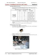
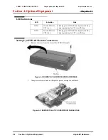
Installing a 24-Button DLS Console

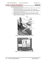
1. The console should be installed on the right-hand side of the phone in order to use the fixing 

plate supplied with the console.

2. Turn the system phone over which will have the 24-Button DLS Console installed.
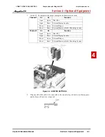
3. If more than one adapter is to be installed on the phone, the console should be installed on the 

connector nearest the right-hand side. Using a flat-head screwdriver, remove the plastic 
punch-out piece covering the connector.

4. Plug the 24-Button DLS Console into the connector on the bottom of the system phone.

5. Push the cable from the console into the cable channel to allow the phone to rest flat.
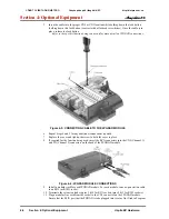
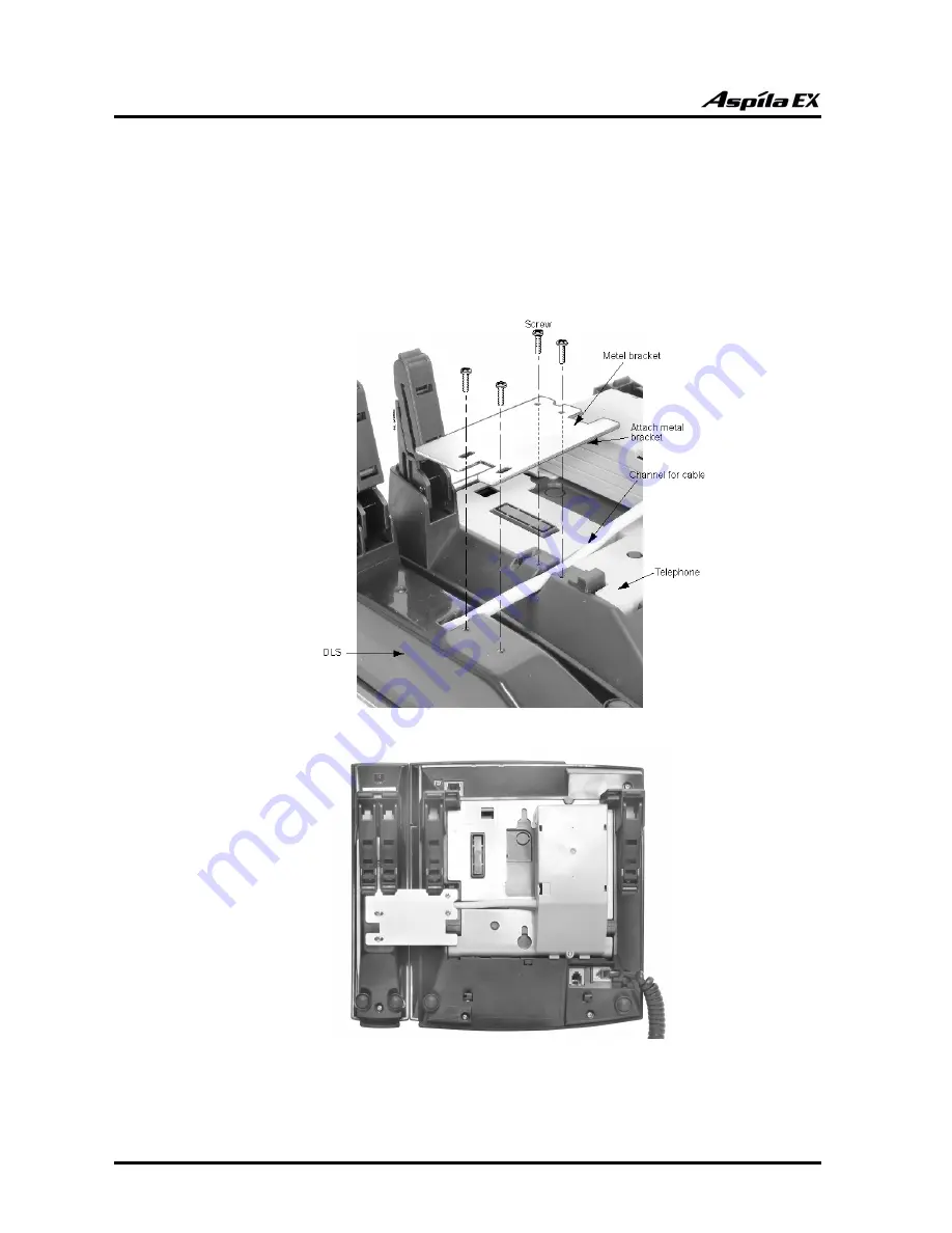
6. Install the fixing plate provided with the 24-Button DLS Console to the bottom of the console 

and phone to join the two sets together. 

Figure 4-12: INSTALLING THE CONNECTOR PLATE

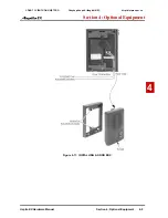
Figure 4-13:  INSTALLED 24-BUTTON DSS CONSOLE

CÔNG TY VIỄN THÔNG VIỆT PRO

Chuyên phân phối tổng đài NEC

http://vietpro.com.vn

Summary of Contents for ASPILA EX

Page 1: ...SMDR 1 Installing Cabinets 3 Installing Extensions and Trunks 4 Optional Equipment 2 PCB Installation and Startup 6 LAN Connection 7 Specifications and Parts C NG TY VI N TH NG VI T PRO Chuy n ph n ph...

Page 2: ...manual is subject to change without notice and NEC Infrontia has no obligation to provide any updates or corrections to this manual Further NEC Infrontia also reserves the right without prior notice t...

Page 3: ...Expansion Cabinets1 31 GROUNDING THE CABINETS1 32 Connecting the System Ground Figure 1 35 1 32 COMPLETING THE INSTALLATION1 34 Reinstalling the Front Cover Figure 1 36 1 34 Section 2 PCB Installation...

Page 4: ...Start 2 56 Section 3 Installing Extensions and Trunks3 1 RJ61 WIRING AND PINOUTS3 2 INSTALLING EXTENSIONS3 3 Digital Extension Cabling3 3 Installing a Key Telephone3 3 INSTALLING SINGLE LINE TELEPHON...

Page 5: ...Adapter Figure 4 27 Figure 4 28 4 28 CTU Adapter Figure 4 31 Figure 4 32 4 29 VoIP Adapter Figure 4 33 Figure 4 35 4 30 POWER FAILURE TELEPHONES4 32 Power Failure Figure 4 36 4 32 SLT ADAPTER4 34 Usin...

Page 6: ...s Aspila EX Hardware Using LANs6 1 Installing a LAN Device or VoIP Telephone6 6 Section 7 Specifications and Parts List7 1 SYSTEM SPECIFICATIONS7 1 PARTS LIST7 8 C NG TY VI N TH NG VI T PRO Chuy n ph...

Page 7: ...on before complet ing the installation process Avoid working with the equipment during electrical storms Use only commercial AC power to prevent shock or fire Use the power cord supplied for the cabin...

Page 8: ...operation for all features on the system Aspila EX Programming Manual How to configure the Aspila EX system System Phone Label Maker Software that allows the installer to customise the button designa...

Page 9: ...e bracket can be used Ensure that enough space is available to allow the installation of an expan sion cabinet above the Main Cabinet The system requires a three prong dedicated 200 240 VAC 50 Hz circ...

Page 10: ...the floor near the MDF within 2 metres of the dedicated AC outlet Do not secure the cabinet to the wall at this time 2 Loosen two front panel retaining screws 3 Slide the front cover to the right the...

Page 11: ...oosen the side panel retaining screws located on the front of the cabinet Remove the side panel covers of the Main Cabinet by pulling out slightly then moving it towards the back of the cabinet to unh...

Page 12: ...gure 1 7 1 Install the wall bracket on the floor providing the appropriate spacing as shown below Figure 1 3 INSTALLING THE MOUNTING BRACKET 2 Secure the mounting bracket to the floor using four 6mm a...

Page 13: ...rdware Manual Section 1 Installing the Cabinets 1 7 1 3 Remove the 2 screws from the front of the mounting bracket Figure 1 5 REMOVE THE SCREWS FROM THE MOUNTING BRACKET C NG TY VI N TH NG VI T PRO Ch...

Page 14: ...Installing the Cabinets Aspila EX Hardware 4 Place the cabinet on the secured mounting bracket and slide backwards Figure 1 6 ATTACHING THE CABINET TO THE MOUNTING BRACKET C NG TY VI N TH NG VI T PRO...

Page 15: ...ction 1 Installing the Cabinets 1 9 1 5 Secure the cabinet to the mounting bracket by reinstalling the two screws removed from the mounting bracket in step 2 Figure 1 7 REINSTALL SCREWS C NG TY VI N T...

Page 16: ...racket to slide over the screw heads It is suggested that plywood first be installed on the wall where the cabinet will be posi tioned This allows for secure anchoring of the screws which will be supp...

Page 17: ...mounting bracket onto the back of the cabinet Figure 1 10 ATTACH BRACKET TO THE CABINET 4 Replace the two screws removed in step 2 to secure the bracket to the cabinet 5 Plug the power cord into the...

Page 18: ...the mounting bracket over the screws attached to the wall Figure 1 11 ATTACHING THE CABINET TO THE MOUNTING BRACKET 7 Secure the cabinet to the wall by inserting the two screws into the bottom half o...

Page 19: ...ely 400mm 9U of height within the rack Figure 1 13 INSTALLING THE MOUNTING BRACKET ON THE RACK Note that the floor wall mounting bracket supplied with each cabinet can be used for rack mouning ONLY IF...

Page 20: ...Section 1 Installing the Cabinets Aspila EX Hardware 2 Remove the two screws from the front of the rack mount bracket Figure 1 14 REMOVE THE SCREWS FROM THE RACK C NG TY VI N TH NG VI T PRO Chuy n ph...

Page 21: ...n expansion cabinet is to be added then you should also connect the 4 wire DC power cable to the BATT2 connector 5 Replace the side panels of the cabinet This must be done at this point as the panels...

Page 22: ...1 Installing the Cabinets 1 16 Section 1 Installing the Cabinets Aspila EX Hardware Figure 1 16 INSTALLING THE CABINET IN THE RACK C NG TY VI N TH NG VI T PRO Chuy n ph n ph i t ng i NEC http vietpro...

Page 23: ...dware Manual Section 1 Installing the Cabinets 1 1 7 Replace the screws in the front of the rack which were removed in step 2 Figure 1 17 SECURING THE CABINET TO THE RACK C NG TY VI N TH NG VI T PRO C...

Page 24: ...y one cabinet should be wall mounted Two cabinets may result in too much weight to be safely mounted together The weight of a two cabinet system can be up to 50kg Before Installing an Expansion Cabine...

Page 25: ...Place the expansion bracket on the top of the main cabinet Using the screws provided with the expansion bracket secure the bracket to the top of the main cabinet Figure 1 19 SECURE THE EXPANSION BRAC...

Page 26: ...REWS FROM THE CABINET 4 Hook the mounting bracket onto the back of the expansion cabinet Figure 1 21 ATTACH BRACKET TO THE CABINET 5 Replace the two screws removed in step 3 to secure the bracket to t...

Page 27: ...the Cabinets Aspila EX Hardware Manual Section 1 Installing the Cabinets 1 1 Figure 1 22 ATTACHING THE EXPANSION CABINET TO THE MOUNTING BRACKET C NG TY VI N TH NG VI T PRO Chuy n ph n ph i t ng i NEC...

Page 28: ...Section 1 Installing the Cabinets Aspila EX Hardware 7 Secure the expansion cabinet to the wall using four screws Figure 1 23 SECURE MOUNTING BRACKET TO THE WALL C NG TY VI N TH NG VI T PRO Chuy n ph...

Page 29: ...et by reinstalling the two screws removed from the expansion bracket in step 1 Figure 1 24 REINSTALL SCREWS 9 On the inside of the front covers loosen the screws for the top or bottom shutters the top...

Page 30: ...and the expansion cabinet BATT2 socket located on the left hand side of each cabinet The DC power cable is required when battery backup is installed it is used to power both cabinets from a single bat...

Page 31: ...S FROM THE BRACKET 2 Place the expansion bracket on the top of the base cabinet Using the screws provided with the expansion bracket secure the bracket to the top of the main cabinet Note that the bas...

Page 32: ...T2 socket located on the left hand side of each cabinet The DC power cable is required when battery backup is installed to allow both cabinets to be powered from a single battery box Unscrew the cable...

Page 33: ...0mm 9U of height within the rack See ATTACHING THE EXPANSION CABINET TO THE MOUNTING BRACKET on page 1 21 for details of fitting the expansion cabinet onto the base cabinet 7 Using the belt provided b...

Page 34: ...EX Hardware 8 Place the cabinets in the rack making sure the hooks on the mounting bracket are inserted into the back of the cabinet securing it in place Figure 1 31 INSTALLING THE CABINETS IN THE RA...

Page 35: ...Hardware Manual Section 1 Installing the Cabinets 1 1 9 Secure the two cabinets by tightening the belt around both cabinets Figure 1 32 SECURING THE CABINETS TOGETHER C NG TY VI N TH NG VI T PRO Chuy...

Page 36: ...1 33 SECURING THE CABINETS TO THE RACK 11 On the inside of the front cover loosen the screws for the top and bottom shutters 12 Slide the shutters to the left to allow a pass through for the EXIFU cab...

Page 37: ...lar cabinet The main cabinet continues to operate normally To turn off power with two cabinets only the power switch on the main cabinet needs to be turned off To Replace the Power Supply Note Remove...

Page 38: ...de of the cabinet on the lower left 1 In each cabinet connect the SG Signal ground lug to the verified Earth Ground point using 14 AWG 2mm2 wire 2 In each cabinet connect the ETH Earth ground lug to t...

Page 39: ...be con nected to the earth when using analogue DID E M or ground start trunk cards in the system The PBXG lugs on both cabinets can share a single cable to Earth ground ETH Earth Ground This ground l...

Page 40: ...Cover Figure 1 36 1 Line up the brackets on the front cover with the slots in the cabinet and insert the cover Figure 1 36 RE INSTALLING THE FRONT COVER 2 Slide the cover to the left Figure 1 37 RE I...

Page 41: ...and rear panel The shutters on the unused pass throughs should be closed in order to help keep dust out of the cabinet 1 Loosen the two screws holding the shutter open 2 Slide the shutter to the left...

Page 42: ...Section 1 Installing the Cabinets 1 36 Section 1 Installing the Cabinets Aspila EX Hardware C NG TY VI N TH NG VI T PRO Chuy n ph n ph i t ng i NEC http vietpro com vn...

Page 43: ...ted for the Expansion PCB Slots 9 16 are universal any type of PCB can be installed Use the table below to determine the PCB for each slot EXIFU 9 10 11 12 13 14 15 16 NTCPU 1 2 3 4 5 6 7 8 Important...

Page 44: ...1 4TLIU DIOPU or BRI PCB s The order in which trunk PCBs are physically inserted determines the numbering plan For example if four PCBs are installed in the following order the numbering plan below wo...

Page 45: ...ts must only be installed with the system power OFF Busying Out Extension Line PCBs The run block switch on extension trunk PCBs busies out idle circuits Extensions lines cannot make a call or be call...

Page 46: ...extension trunk PCB with the system running 1 Set the run block switch to BLOCK 2 When the STATUS LED stops flashing all extensions trunks are idle 3 Remove the PCB by lifting the white pull clip on...

Page 47: ...no ground start 16 per system 4COIU LG1 4 Analogue Loop Start Trunks with ground start 16 per system 8COIU LG1 8 Analogue Loop Start Trunks with ground start 16 per system 2BRIU 2 Two Channel BRI Cir...

Page 48: ...sion Multiplex Switch TDM Switch Digital Phase Locked Loop DPLL Tone Generator DTMF Tone Sender Receiver 32 Channels System Tone Sender DTMF Tone Sender Call Progress Tone Detector Conference 64 Chann...

Page 49: ...tion 2 PCB Installation and Startup Aspila EX Hardware Manual Section 2 PCB Installation and Startup 2 7 2 Figure 2 3 CPRU PCB C NG TY VI N TH NG VI T PRO Chuy n ph n ph i t ng i NEC http vietpro com...

Page 50: ...PRI Trunk PCB E M Trunk PCB Networking Feature 16VOIPU PCB IP1E NTCPU A1 Trunk and ESIU SLIU extension port Combined maximum of 64 ports DECT and IP extension port Combined maximum of 64 ports Virtua...

Page 51: ...g software stored on the NTCPU SW2 Reset Switch The system resets when the toggle switch is lifted and released using the stored software and customer data on the NTCPU Hot Start SW3 1 Must be set to...

Page 52: ...ng Serial Cable Connector CN1 D Sub 9 Pin Male Pin No Signal 1 DCD 2 RxD 3 TxD 4 DTR 5 GND 6 DSR 7 RTS 8 CTS 9 USB Cable Connector CN13 Standard Pin No Signal 1 Vcc 2 D 3 D 4 GND Ethernet Cable Connec...

Page 53: ...4 and 5 External Paging Output Pins 2 and 7 External Music on Hold Input Input Impedance 47 kohm 1 kHz RJ61 Cable Connector CN17 External Speaker and Night Mode Relay NTCPRU Connector Modular Connect...

Page 54: ...always be facing to the right side of the cab inet away from the power supply 5 If external BGM or MOH is being installed plug an RJ61 connector into the CN16 connector on the NTCPU The other end of t...

Page 55: ...d to reload the customer data if necessary Note that a PC ATA card can only hold one customer database Each database to be saved will require its own separate card ALternatively the database can be co...

Page 56: ...o connect the main cabinet and expansion cabinets together To install an EXIFU PCB 1 Ensure that both the Main and expansion cabinets are powered off 2 Install the EXIFU into the CPU EXP slot in the e...

Page 57: ...t must have the compact flash card installed To install a DSPDB Daughter Board 1 Power off the Main cabinet and remove the NTCPU card 2 Included with the DSPDB are four spacers Install one spacer in e...

Page 58: ...e the DSPDB Compact Flash Card 1 With the system power off remove the NTCPU 2 Remove the compact flash card from the DSPDB daughter board 3 Insert the new compact flash card 4 Reinstall the NTCPU Figu...

Page 59: ...h provide connection to 4 digital station ports With the 8ESIU PCB the CN202 and CN203 connectors and the BL3 and BL4 LEDS are removed from the PCB In order to program the system with a multibutton te...

Page 60: ...e PCB Pull Tab should always be positioned closest to the top of the cabinet 3 Set the ESIU run block switch to run UP 4 The 8ESIU will use the first block of 8 extension ports available the 16ESIU wi...

Page 61: ...5 03 03 to 1 special terminal to allow DTMF tones during call The CN3 and CN5 connectors each provide connection to 4 analogue station ports which are not polar ity sensitive The 8SLIU is installed in...

Page 62: ...rting the 8SLIU PCB into the cabinet 2 Install the 8SLU into the slot Note that the white PCB Pull Tab should always be positioned closest to the top of the cabinet 3 Set the 8SLIU s run block switch...

Page 63: ...ring call The CN3 and CN5 connectors each provide connection to 4 analogue station ports and are not polarity sensitive The 8SLIDB is installed on the 8SLIU PCB with 16 maxi mum per system Connector P...

Page 64: ...aughter board so when installed the components are facing the 8SLIU PCB 2 Position the 8SLIDB s CN1 connector over the CN9 connector on the 8SLIU PCB Press the boards together ensuring the plastic spa...

Page 65: ...G1 analogue ground start line trunk circuits 4 4COIU LG1 or 8 8COIU LG1 trunk status LEDs 4 4COIU LG1 or 8 8COIU LG1 Caller ID Circuits 2 4 8COIU LG1 Power Failure Transfer Circuits 1 PCB status LED 1...

Page 66: ...ircuit 1 Tip 6 Circuit 2 Ring 7 Circuit 3 Ring 8 Circuit 4 Ring RJ61 Cable Connector CN5 Trunks 8COIU Only Pin No Connection 1 Circuit 8 Tip 2 Circuit 7 Tip 3 Circuit 6 Tip 4 Circuit 5 Ring 5 Circuit...

Page 67: ...of the cabinet 3 Set the COIU run block switch to run UP With normal operation the status LED will flash fast If trouble was found during the self diagnostics routine the status LED will flash slowly...

Page 68: ...rovides 4 4DIOPU or 8 8DIOPU DID trunk circuits 4 4DIOPU or 8 8DIOPU DID trunk status LEDs 1 PCB status LED 1 run block switch The CN3 and CN5 connectors each provide connection to 4 analogue DID trun...

Page 69: ...e top of the cabinet 3 Set the run block switch to run UP With normal operation the status LED will flash fast If trouble was found during the self diagnostics routine the status LED will flash slowly...

Page 70: ...nks and it can be plugged into any universal slot The PCB contains 2 straps and 1 switch How these items are set determines the type of signaling the system uses The type of lines the central office p...

Page 71: ...gnal from trunk 8 SG Ground wire for control RJ61 Cable Connector 4 Wire E M CN100 CN400 Pin No Connection Description 1 SB Ground wire for control 2 M Control signal to trunk 3 R Voice signal to trun...

Page 72: ...2 PCB Installation and Startup 2 30 Section 2 PCB Installation and Startup Aspila EX Hardware Man Signaling Method for Circuit Types C NG TY VI N TH NG VI T PRO Chuy n ph n ph i t ng i NEC http vietpr...

Page 73: ...Section 2 PCB Installation and Startup Aspila EX Hardware Manual Section 2 PCB Installation and Startup 2 31 2 C NG TY VI N TH NG VI T PRO Chuy n ph n ph i t ng i NEC http vietpro com vn...

Page 74: ...Installation and Startup 2 32 Section 2 PCB Installation and Startup Aspila EX Hardware Man Voice Signal Connection for all Circuit Types C NG TY VI N TH NG VI T PRO Chuy n ph n ph i t ng i NEC http v...

Page 75: ...a slot Note that the white PCB Pull Tab should always be positioned closest to the top of the cabinet 5 Set the run block switch to run UP With normal operation the status LED will flash fast If troub...

Page 76: ...of the Tx Rx of each circuit is set by SW102 through SW802 switch settings on the BRI PCB When used for S Bus a maximum of 8 ISDN terminals can be con nected to each circuit The first 4 circuits 1 4 a...

Page 77: ...selected and if the Aspila EX system is not connected to the last port of the Bus connection this switch should be OFF CN102 CN202 CN302 CN402 ON With S Bus selected the Feeding Power is supplied to t...

Page 78: ...ositioned closest to the top of the cabinet 6 Set the run block switch to run UP Before proceeding to Step 7 wait to verify that the STA TUS LED starts to flash With normal operation the status LED wi...

Page 79: ...y use trunks 9 40 If you have COIU PCBs installed for trunks 1 8 and 17 24 the PRI PCB will use trunks 25 56 The PRI Interface PCB cannot use trunks 9 16 even if available since they are not part of a...

Page 80: ...rdware Man Connector Pin Outs on 1PRIU PCB RJ45 Cable Connector CN3 S Bus Connection Pin No Connection 1 TA 2 TB 3 4 RA 5 RB 6 7 8 RJ45 Cable Connector CN3 T Bus Connection Pin No Connection 1 RA 2 RB...

Page 81: ...any universal slot Note that the white PCB Pull Tab should always be positioned closest to the top of the cabinet 6 Set the run block switch to run UP With normal operation the status LED will flash...

Page 82: ...for HDD access Power monitor LED Server status LED PCMCIA card slot Run Block switch Server reset switch used to reset the server when necessary CRT connector WAN connector RJ 45 LAN connector PS 2 mo...

Page 83: ...suspended or is ready to be removed HDD HDD Access Red Steady Accessing the HDD LED 1 Power Monitor Supervising Power Off Normal working Red Steady Power shutdown condition LED 2 Server Status Superv...

Page 84: ...nector When using an HDD or IDE Flash Memory it should have an OS operating system installed and application software Figure 2 17 INSTALLING THE APSU PCB 3 To insert the PC ATA card simply slide the c...

Page 85: ...PCB The PCB plugs into a universal slot with a maximum of 6 PCB per system Each PCB provides 8 RJ45 port connectors These are used to connect to LAN terminals Depending the on the type of LAN ter min...

Page 86: ...at the white PCB Pull Tab should always be positioned closest to the top of the cabinet 3 Set the RUN BLOCK switch to run UP With normal operation the status LED will flash fast If trouble was found d...

Page 87: ...PCB status LED 1 run block switch A maximum of 6 PCBs per system are allowed providing 96 channels with the daughter board 192 channels it can be plugged into any universal slot If a separate software...

Page 88: ...D will flash fast If trouble was found during the self diagnostics routine the status LED will flash slowly 4 The 16VOIPU PCB will use the first block of 16 trunk ports available Confirm the ports use...

Page 89: ...he front of the daughter board so when installed the compo nents are facing the 16VOIPU PCB 2 Position the VOIPDB S CN6 connector over the CN12 connector on the 16VOIPU PCB The CN5 connector on the VO...

Page 90: ...s and LED Indications on page 2 9 for NTCPU LED status 6 Wait about three minutes for the system to boot The telephone display at extension 200 will show the Time Date and extension number when the bo...

Page 91: ...k PCBs are physically inserted determines the num bering plan For example if four PCBs are installed in the following order the numbering plan below would apply Installing PRI PCBs The PRI Interface P...

Page 92: ...nel switch to ON Refer to Switch Settings and LED Indications on page 2 9 for NTCPU LED status 4 Wait about three minutes for the system to boot The telephone display at extension 200 will show the Ti...

Page 93: ...e Programming Mode Enter the system programming mode at any system phone with an LCD display 1 Press CALL1 You hear dial tone 2 Dial 3 Dial the system password 4 Press HOLD The system allows up to two...

Page 94: ...he system s programming 3 The display shows Complete Data Save when completed and will exit the phone to an idle mode Upgrading Your Software 1 Insert the PC ATA card containing the software upgrade i...

Page 95: ...Section 2 PCB Installation and Startup 2 53 2 Making Test Calls In the initial configuration All Programmable Function keys are line keys e g key 1 is line 1 All trunks are loop start DTMF C NG TY VI...

Page 96: ...o cabinets are used 8 Check and verify the correct LED indication on the PCB 9 Check and verify extension PCB installation To troubleshoot lines 1 Verify the Run Block switch is set in the RUN positio...

Page 97: ...Running program 90 13 03 in MAINTENANCE PROGRAMS prints a system PCB report Refer to Program 90 13 03 System Information Output in the Software Manual The following is a typical report SYSTEM INFORMAT...

Page 98: ...rts are installed they will become operational All user s setting e g call forward camp on etc will be kept Resetting the System Hot Start Observe the following when resetting the system DO NOT reset...

Page 99: ...Trunks 3 1 3 Section 3 Installing Extensions and Trunks Section 3 Installing Extensions and Trunks Important Install telephones as on premise extensions only Otherwise the telephones are highly susce...

Page 100: ...NTCPU ESIU SLIU SLIDB COIU DIOPU TLIU The RJ61 wiring pinouts and colour codes of RJ61 are shown in Table 1 RJ61 Pinouts Colour Codes on page 3 2 Table 1 RJ61 Pinouts Colour Codes Pin Number RJ61 Col...

Page 101: ...line cord supplied 2 For each extension run one pair station cable to an RJ11 or RJ45 socket 3 Terminate the pair to pins 3 4 for the RJ11 socket pins 4 5 of the RJ45 socket Refer to Digital Station 8...

Page 102: ...maximum cable lengths Installing a Single Line Telephone To install a single line telephone 1 Install a line jack for each single line telephone The line jack should be within two metres of the phone...

Page 103: ...ds must be connected as described on page 1 32 or the trunks will not function correctly When connecting the RJ61 cables to the COIU PCB note the position of the Power Failure con nector Do not confus...

Page 104: ...tor on the BRI card If more than one terminal is connected run a 2 pair cable to an RJ45 socket then daisy chain the connection to the additional ISDN terminals For pin out information for S Bus conne...

Page 105: ...ed directly into the NT1 Termination Use an RJ45 patch cable 2 For S Bus Mode The ISDN PRI device can be plugged directly into the RJ45 connector on the BRI card For pin out information for S Bus mode...

Page 106: ...DID TRUNKS DID Trunks Installing DID Trunks 1 For each trunk run one pair cable from the PSTN Network Termination point to the DIOPU PCB Refer to Direct Inward Dial DID 4 8DIOPU PCB Figure 2 13 page...

Page 107: ...Figure 2 14 page 2 28 for details of the RJ61 con nector pin outs Note that two pins of the RJ 61 connector are not used for 2 wire tie lines 2 Make sure the strapping on the 4TLIU PCB is set to the...

Page 108: ...ing Ferrites to Tie Line Cables 1 Four ferrite sleeves are supplied with the TLIU PCB 2 Each cable that will be connected to the TLIU PCB must pass two times one turn through a ferrite sleeve to compl...

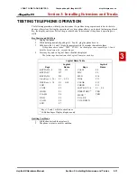
Page 109: ...release them If the phone doesn t show TEST PUSH on the display then repeat Steps 1 3 and hold the keys down a few seconds longer 4 Press any key and its Logical Name should be displayed The following...

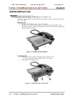
Page 110: ...f the phone 2 You ll hear a click when it locks into the first position If you wish the display to be at a higher angle continue to lift the LCD display until a second click is heard This is the highe...

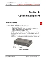
Page 111: ...ording System 96 maximum per system The 2PGDAD module also provides multi purpose controls These control relays can be used for con trolling the external amplifier external music source and door lock...

Page 112: ...crewdriver break out the plastic piece covering the cable hole Figure 4 3 REMOVE PLASTIC COVER FROM CABLE HOLE LED Indication Note LED 1 Green LED when CH1 in use Flashing green LED indicates dipswitc...

Page 113: ...y or door box so that approxi mately 8 mm of bare wire is exposed Channel1 S3 S4 Function Open Open Door Box Open Short External Paging Speaker Short Open External Ringer Short Short External Music on...

Page 114: ...cover and tighten the screw to hold the cover in place 8 If required for the function being used insert the RCA connectors into the CN3 Channel 1 and CN Channel 2 connectors on the back of the 2PGDAD...

Page 115: ...DAD module insert two wood screws 100mm apart Leave 3mm of the screw exposed The screws can be installed either vertical or horizontal depending on which position fits best for your location Figure 4...

Page 116: ...ephones If an extension user activates it BGM plays whenever the user s extension is idle 1 Connect an RJ61 modular line cord from the CN16 connector on the NTCPU to the appropri ate location on the b...

Page 117: ...ete Steps 3 4 Otherwise skip to Step 7 3 Install an RJ11 or RJ45 socket for each 2PGDAD module For each module run one pair station cable to the RJ11 or RJ45 socket 4 Terminate the extension leads to...

Page 118: ...ection 4 Optional Equipment 4 8 Section 4 Optional Equipment Aspila EX Hardware Figure 4 10 SETTING THE 2PGDAD FOR A DOOR BOX C NG TY VI N TH NG VI T PRO Chuy n ph n ph i t ng i NEC http vietpro com v...

Page 119: ...Section 4 Optional Equipment Aspila EX Hardware Manual Section 4 Optional Equipment 4 9 4 Figure 4 11 INSTALLING A DOOR BOX C NG TY VI N TH NG VI T PRO Chuy n ph n ph i t ng i NEC http vietpro com vn...

Page 120: ...10 button DSS Consoles As the 24 button DLS Console is connected to the system phone an extension can only have one 24 button DLS Console installed An extension can have both a 24 button DLS Console a...

Page 121: ...p The system automatically assigns the terminal type 10 for the port which has a DSS console installed When installing a DSS the system must auto detect the console in order for the LEDS to function c...

Page 122: ...alled on the connector nearest the right hand side Using a flat head screwdriver remove the plastic punch out piece covering the connector 4 Plug the 24 Button DLS Console into the connector on the bo...

Page 123: ...also be used for an ana logue Door Box Installing an External Page System 1 Connecting to the NTCPU Connect an RJ61 modular line cord from the CN16 connector on the NTCPU to the appropri ate location...

Page 124: ...ment Aspila EX Hardware Figure 4 14 2PGDAD CABLE CONNECTION Note Page amplification is not provided by the 2PGDAD module and must be accommodated by using an external page amplifier C NG TY VI N TH NG...

Page 125: ...o Step 5 3 Install an RJ11 or RJ45 socket for each 2PGDAD module For each module run one pair station cable to pins 3 4 for RJ11 sockets pins 4 5 for RJ45 4 Plug a modular line cord from the socket to...

Page 126: ...rom handsfree The headset plugs into a separate RJ11 4 4way on the bottom of the phone This allows the use of the handset or headset whichever is convenient at the time Note that the headset socket is...

Page 127: ...r easy printing by any printer dot matrix laser etc Removing the Faceplate 1 At the lower right hand corner of the telephone you ll notice a small notch in the faceplate plastic Use this notch to help...

Page 128: ...t allows the MOH source e g a tape deck to run only when a call is placed on Hold The maximum applied voltage for the relay is 24vDC at 5A the relays are normally open and close when a call is put on...

Page 129: ...Section 4 Optional Equipment Aspila EX Hardware Manual Section 4 Optional Equipment 4 19 4 Figure 4 17 2PGDAD CONNECTIONS C NG TY VI N TH NG VI T PRO Chuy n ph n ph i t ng i NEC http vietpro com vn...

Page 130: ...v DC at 7mA The NTCPU will detect from 5V DC to 48VDC Refer to Night Service in the Software Manual for additional details Connecting a Night Mode Selector Switch 1 Connect an RJ61 modular line cord f...

Page 131: ...rs can not be used together When installing the adapters the system phone should first be unplugged from the system Also note that the adapters may have an AC DC power jack Power is not required for a...

Page 132: ...be necessary to remove the cover from an adapter First remove the screw on the back of the adapter 2 Using a small screwdriver push in the ribs on the sides of the adapter Do not push the ribs in too...

Page 133: ...o the required position The SW1 and SW2 switches should be set to 1 for either application CAUTION Be sure the connected audio device provides a standard AUX level input The use of monitoring recordin...

Page 134: ...h the ribs in too much or they may break Figure 4 21 REMOVE THE SCREW FROM THE ADA ADAPTER 5 Determine which terminals should be connected Terminals T6 and T7 are used for wiring to a recorder If usin...

Page 135: ...te must be located on the cable as near as possible to the ADA adaptor 11 Position the adapter with the connector positioned as shown below Figure 4 26 POSITIONING THE ADAPTER 12 Hook the two plastic...

Page 136: ...t for connection of the single line analogue device connection to a suitable Master type line jack unit may be required for some analogue devices Neither the APA or APR Adapter supports reverse polari...

Page 137: ...uded with the APA APR Adapter wrap the line cord once through the ferrite bead and snap it shut 10 Plug the end of the line cord for the analogue device which has the ferrite bead closest to it into t...

Page 138: ...P SWITCH SETTINGS 4 Position the adapter with the connector positioned as shown below Figure 4 30 POSITIONING THE ADAPTER 5 Hook the two plastic prongs into the bottom of the phone 6 Push the connecto...

Page 139: ...on the CTU adapter to the required position The DSW settings are 1 on 2 8 off for a PC connection or 1 and 2 on 3 8 off for a printer connection factory setting is for a PC connection Figure 4 31 RECO...

Page 140: ...co If a separate software hub is used and not the 8SHUBU PCB it should be a 100Base full duplex hub To avoid network problems and to ensure good voice quality do not use a Repeater Hub 10Base Installi...

Page 141: ...f the adapter should lock into place when it is properly positioned 7 Plug an AC DC adapter into the AC jack on the adapter if power is not supplied by the LAN 8 Plug in the LAN straight thru cable fr...

Page 142: ...sfer circuit or using the 8COIU LS1 or 8COIU LG1 PCB 2 circuits are provided The CN3 and CN5 connectors each provide connection to 4 analogue trunk ports A maximum of 16 4 8COIU LS1 PCBs per system is...

Page 143: ...a Master type socket for each single line telephone supporting PF operation The socket should be within 2 mteres of the phone 3 For each extension run one pair station cable from the RJ61 connector t...

Page 144: ...one pair station cable for each SLT Adapter 2 Connect the cable to the corresponding RJ 61 connector on the ESIU PCB 3 Install a Master type socket for the SLT Adapter within 2 metres of the mod ule s...

Page 145: ...pter 2 Fix the two screws provided with the SLT Adapter as shown in the diagram below leaving 3mm protruding from the wall 3 Attach the SLTAD to the screws 4 Plug the two modular line cords back into...

Page 146: ...set to the third position starting when set at the first position Fold the leg down and slightly pull the extension out Tip the extension down then slide it back until the slide reaches the opposite...

Page 147: ...t Aspila EX Hardware Manual Section 4 Optional Equipment 4 37 4 Figure 4 40 SETTING THE LEGS POSITION 2 Figure 4 41 EXPANDING THE LEG HEIGHT POSITION 3 C NG TY VI N TH NG VI T PRO Chuy n ph n ph i t n...

Page 148: ...ment 4 38 Section 4 Optional Equipment Aspila EX Hardware Figure 4 42 EXTENDING THE LEGS POSITION 3 Figure 4 43 SETTING THE LEG POSITION POSITION 3 C NG TY VI N TH NG VI T PRO Chuy n ph n ph i t ng i...

Page 149: ...t be wall mounted The bracket will not accommodate the adapter s Installing the Wall Mount Handset Bracket Figure 4 44 Figure 4 46 1 Remove the integrated wall bracket from the bottom of the phone Ref...

Page 150: ...INSTALLING THE HOOKSWITCH HANGER Wall Mounting the Phone Figure 4 50 Figure 4 50 1 After removing the integrated wall bracket from the bottom of the phone Figure 4 44 attach the wall bracket to the wa...

Page 151: ...re 4 47 ATTACHING THE BRACKET 2 Attach the phone to the wall mount bracket by inserting the bottom hooks indicated by A in Figure 4 48 BRACKET HOOKS on page 4 41 on the bracket into the back of the ph...

Page 152: ...ection 4 Optional Equipment 4 42 Section 4 Optional Equipment Aspila EX Hardware Figure 4 49 PLACING THE PHONE ON THE BRACKET C NG TY VI N TH NG VI T PRO Chuy n ph n ph i t ng i NEC http vietpro com v...

Page 153: ...ushing the top towards the wall insert the top hooks into the back of the phone Figure 4 50 COMPLETED WALL MOUNT BRACKET INSTALLATION 4 Insert the telephone s line cord from the RJ11 RJ45 socket into...

Page 154: ...a Wall Mounting Bracket Figure 4 51 Figure 4 52 1 Grip the system phone on both sides in the location shown below by A Figure 4 51 GRIP THE SYSTEM PHONE 2 Lift the phone up The wall mount bracket wil...

Page 155: ...bracket hooks C then unhook the bottom hooks D Figure 4 52 REMOVING THE SYSTEM PHONE FROM THE WALL MOUNT BRACKET 4 Move the phone down to remove it from the bottom bracket hooks It is important to not...

Page 156: ...Section 4 Optional Equipment 4 46 Section 4 Optional Equipment Aspila EX Hardware For Your Notes C NG TY VI N TH NG VI T PRO Chuy n ph n ph i t ng i NEC http vietpro com vn...

Page 157: ...ters cannot be installed on the same system phone as only one voice path is provided by the system phone for the adapters The maximum distance between the APA Adapter and the analogue terminal is 15 m...

Page 158: ...unication Availability With Hardware Functions NTCPU Port CTA APSU Serial USB Ethernet Windows PC Programming Yes Yes Yes No No Web Programming for Installer Yes Yes Yes No No Web Programming for User...

Page 159: ...1 is set to CTA enter the extension number with the CTA connec tion 90 13 03 System Information Output Output Command Dialing 1 from this program sends the system report to the connected device 90 12...

Page 160: ...e DCI device to be used refer to the specific CTA CTU information described previ ously 2 Install the SMDR recording device according to the manufacturer s instructions 3 Connect the SMDR recording de...

Page 161: ...Call Enter 1 if you want the SMDR report to include calls blocked by Toll Restriction Enter 0 to exclude blocked calls 35 02 02 SMDR Output Options PBX Calls If system is behind a PBX enter 1 to have...

Page 162: ...utput Output Port Type Indicate the type of connection used for the SMDR 0 No setting 1 COM port NTCPU 2 USB port NTCPU 4 CTA CTU 90 13 02 System Information Output Destination Extension Number If the...

Page 163: ...e TX To connect a telephone to a LAN connection the system allows the use of either an Aspila EX digital system phone with an IP Adapter installed or an H 323 IP digital telephone For details on insta...

Page 164: ...numbers in the IP address as it is defining the network location of the final destination So for example if the IP Address were 172 16 0 10 and the Subnet Mask used was Class B 255 255 0 0 the first...

Page 165: ...er or if over 50 outer addresses must be registered Otherwise the Aspila EX provides tables within the system programming for address reso lution IP Hardware PCBs NTCPU Signals the gateway with VoIP c...

Page 166: ...H 323 Phone Registration and Routing VLAN Tag and port based VLAN VoCoder G 711 law a law G 729a G 723 1 Fax Relay Jitter Buffer Size Set by system programming RTP Length Set by system programming Ech...

Page 167: ...ch NEC BF200 24 l PoE Power over Ethernet to Legacy IP Uniden H 323 Phone l Spare Pair 4 5 7 8 Signal Pair 1 2 3 6 Selection 12 Port Power Supply Patch Panel NEC SN1604 PWRMS l PoE Power over Ethernet...

Page 168: ...h which will provide the net work connection to the IP telephone or PC 2 Connect the RJ 45 modular jack on the opposite end of the cable to the IP telephone or PC s network interface card NIC 3 If loc...

Page 169: ...256 256 Total extension ports 512 combined total to 256 in addition to the digital or analogue ports 24 Button DLS Consoles 110 Button DSS Consoles 256 32 Conference Circuits 64 32 parties max per Co...

Page 170: ...Digital Stations 16 4TLIU 4 E M Tie Line Trunks 16 16ESIU16 Digital Stations 16 4DIOPU 4 DID OPX Trunks 16 8SLIU 8 Analogue Stations 16 8DIOPU 8 DID OPX Trunks 16 8SLIDB 8 Analogue Stations Daughter...

Page 171: ...2 104o F Humidity 10 90 RH CAUTION The VMSU A1 and APSU A1 exceptions They are limited to 5o C 40o C 41 104o F Door Box Temperature 20o C 60o C 4 140o F Humidity 20 80 non condensing Power Supply Oper...

Page 172: ...3 42VDC 3 1 5VDC 2 48VDC 5 Output Current 1 0 0A 6 0A 0 0A 5 0A 0 0A 1 0A Output Current 2 0 0A 3 2A 0 0A 1 0A 0 0A 2 0A Ripple Noise 50mV p p 100mV p p 200mV p p Overvoltage Protection 3 7 8 0V 5 6...

Page 173: ...mV 10 dBm 1V RMS Inputs for MOH and BGM are located on the NTCPU PCB The 2PGDAD also provides MOH inputs Door Box External Paging Output Impedance Output Level Maximum Output Configuration 600 Ohm No...

Page 174: ...X and cross connect blocks should install to the right of the Main Cabinet Extension blocks and cross connect blocks should be installed to the left of the Main Cabinet Cable Requirements Device Cable...

Page 175: ...AN UTP cable with category 3 or more for 10Base T and category 5 or more for 100 Base TX 15 PC to CTA Serial Straight Thru Cable 1 5 16VOIPU PCB to IP Telephone and Router Standard Ethernet Cable 100...

Page 176: ...n DLS Console Black 24 Button DLS Console White 110 Button DSS Console Black 110 Button DSS Console White 0890047 0890048 0890041 0890042 0890043 0890044 0890045 0890046 0890049 0890050 0890065 089006...

Page 177: ...6 Aspila EX Digital Station PCB 16 i Series Digital Station PCB Not available 8 Analogue Station PCB 8 Analogue Station Expansion Daughter Board 2 Port Aspila EXmail PCB 4 Port Aspila EXmail PCB 4 Por...

Page 178: ...Section 7 Specifications and Parts List 7 10 Section 7 Specifications and Parts List Aspila EX Hardware C NG TY VI N TH NG VI T PRO Chuy n ph n ph i t ng i NEC http vietpro com vn...

Page 179: ...net Expansion 1 18 Before Installing 1 18 Cabinet Main 1 3 Cabinets Grounding 1 32 Cable Requirements 7 6 7 7 Cabling Extension 3 3 Ground Start Loop Start 3 5 Single Line 3 4 Cabling Requirements 7 6...

Page 180: ...l Programming 2 51 Install PRI Interface PCB 2 39 Installation APSU 2 42 CPRU 2 12 PCBs 2 3 Installing 2 4 8BRI Interface PCB 2 36 4 8COUI LS1 PCB 2 23 4TLIU PCB 2 33 8SHUBU 2 44 8SLIDB Daughter Board...

Page 181: ...2 19 Analogue Station Daughter Board 2 21 2 40 Digital Station 2 17 Direct Inward Dial DID 2 26 DSPDB Daughter Board 2 15 Expansion 2 14 LAN 8 Port Switching Hub 2 43 PRI 2 37 Removing an Extension o...

Page 182: ...lling 5 4 Programming 5 5 SMDR and Data 5 1 Software Upgrading 2 52 Specifications 2PGDAD Module NTCPU Input Output 7 5 BGM MOH Source Input 7 5 Cable Requirements 7 6 7 7 Cabling Requirements 7 6 Doo...

Page 183: ...e Legs 4 36 Using the Wall Mount Bracket 4 39 V Voice over IP VOIPU PCB 2 45 VoIP Adapter 4 30 VoIP Hardware 6 3 VOIPDB PCB 2 47 VOIPU 2 45 W Wall Mount Installing the Handset Bracket 4 39 Wall Mount...

Page 184: ...Index 6 Index Aspila EX Hardware C NG TY VI N TH NG VI T PRO Chuy n ph n ph i t ng i NEC http vietpro com vn...

Page 185: ...C NG TY VI N TH NG VI T PRO Chuy n ph n ph i t ng i NEC http vietpro com vn...

Page 186: ...frontia Asia Pacific Sdn Bhd 24 Jalan Juruhebah U1 50 Temasya Industrial Park Phase 2 Seksyen U1 Glenmarie 40150 Shah Alam Selangor Darul Ehsan Malaysia 603 5569 5888 C NG TY VI N TH NG VI T PRO Chuy...

Reviews: