Section 2: PCB Installation and Startup
Aspila EX Hardware Manual
Section 2: PCB Installation and Startup
2-9
2
Switch Settings and LED Indications
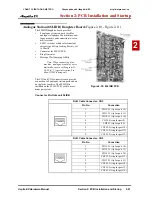
The LED indications on the NTCPU represent the following:
•
RUN LED 1 = Indicates the NTCPU is operating
•
LED 0, 2 and 3 = Indicate system alarms
•
LED 4 = Indicates the status of the PCMCIA slot (off with no PC-ATA card installed)
Switch
Switch
Setting
Operation
SW1 - Load Switch
Push Switch
-
With a system restart or a system reset while holding the SW1
switch (SW3-2 switch set to off):
• With a flash card installed: System software is updated from the
flash card to the NTCPU.
• Without a PC-ATA: System boots loading software stored on the
NTCPU.
• With a Card Other Than a PC-ATA: The card is ignored and the
system boots loading software stored on the NTCPU.
With a system restart or a system reset without holding the SW1
switch:
• The system boots loading software stored on the NTCPU.
SW2 - Reset Switch
-
The system resets when the toggle switch is lifted and released using
the stored software and customer data on the NTCPU (Hot Start).
SW3 - 1
Must be set to OFF
On
Off
Debugging Mode (CN1 connector used for debugging)
Normal Mode (CN1 connector used for serial interface)
SW3 - 2
Must be set to OFF
On
Off
(Factory Use) Used to initially load system software
Normal Mode
LED Indication
Status
RUN (LED1)
LED0
LED2
LED3
LED4
On
Off
Off
Off
-
System starting up
Off
Off
Off
Off
-
System initializing
Off
On
Off
Access Blink
-
Initializing the disk or formatting
Off
Off
On
On
-
Boot program is initializing in the
flash memory
Off
On
On
Access Blink
-
Reading system software
On
Blinking
Blinking
Blinking
-
Upgrading system software
On
Blinking
Off
Off
-
Upgrading boot software
On
Blinking
Blinking
Off
-
Finish formatting (SRAM, Flash)
Blinking
Off
Off
Off
-
DRAM error
Blinking
Off
Off
On
-
FPGA version error
Blinking
Off
On
Off
-
SRAM error
Blinking
Off
On
On
-
Flash memory booting error
CÔNG TY VIỄN THÔNG VIỆT PRO
Chuyên phân phối tổng đài NEC
http://vietpro.com.vn


