Section 2: PCB Installation and Startup
Aspila EX Hardware Manual
Section 2: PCB Installation and Startup
2-3
2
PCB INSTALLATION
Handling the PCBs
The PCBs are sensitive to static discharge. To minimize static discharge, keep PCBs in static free bags
when not installed. Observe the following when installing or removing a PCB:
•
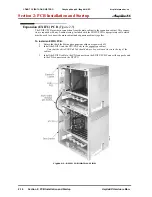
Ground Main Cabinet and Expansion Cabinets
•
Wear a grounded wrist strap to install/remove any PCBs
•
Do not touch PCB components. Handle with card pulls or card edges.
•
Although it is recommended to installed the PCBs with the system power off, all PCBs can be
installed hot
(except the CPRU, 4VMSU, 2/4FMSU, and APSU PCBs).
•
The power supply units must only be installed with the system power OFF.
"Busying Out" Extension/Line PCBs
The run/block switch on extension/trunk PCBs "busies out" idle circuits. Extensions/lines cannot make
a call or be called. Calls in progress before the PCB is "made-busy" are not affected. The PCB can be
pulled out without interrupting a call in progress.
An extension/line PCB Status LED:
•
Normally flashes
•
Lights steady when "made-busy" with an extension/line in use
•
Goes out when the all extensions/lines are "made-busy" (idle)
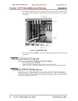
Installing an Extension or Trunk PCB
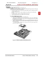
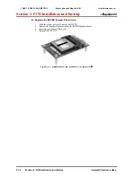
(Figure 2-1, Figure 2-2)
To install an extension/trunk PCB with the system running:
1. Set the run/block switch to
BLOCK.
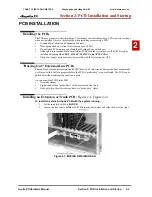
2. Loosen the two screws holding the PCB retaining bar in place and slide the bar to the right.
Figure 2-1: MOVING RETAINING BAR
CÔNG TY VIỄN THÔNG VIỆT PRO
Chuyên phân phối tổng đài NEC
http://vietpro.com.vn


