Section 2: PCB Installation and Startup
2-42
Section 2: PCB Installation and Startup
Aspila EX Hardware Man-
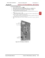
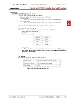
In-Skin Server/Router PCB Installation
(Figure 2-17)
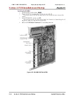
1. Install the battery on the APSU PCB. The polarity “+” symbol must be on top.
2. If required, install the HDD or IDE Flash Memory to the CN4 connector.
When using an HDD or IDE Flash Memory, it should have an OS (operating system)
installed and application software.
Figure 2-17: INSTALLING THE APSU PCB
3. To insert the PC-ATA card, simply slide the card into the CN16 card slot, pushing firmly to
ensure proper connection.
To remove the card set the run/block switch to BLOCK and wait for the Status LED to turn off
before removing the card, this may take up to 3 minutes.
CÔNG TY VIỄN THÔNG VIỆT PRO
Chuyên phân phối tổng đài NEC
http://vietpro.com.vn


