Section 4: Optional Equipment
Aspila EX Hardware Manual
Section 4: Optional Equipment
4-15
4
EXTERNAL PAGING AND PAGE RELAYS
External Page Relays
Two external dry contact relays are available when a 2PGDAD is installed which can be used to activate
ancillary devices (i.e. door unlock devices). The relays on the 2PGDAD modules are numbered 1-8.
Each Door Box/external page circuit provides a dry relay contact.
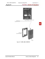
Door Box /External Page Relay Contacts
(Figure 4-15)
To connect a dry contact relay device to a Door Box/External Page Relay:
1.
Connecting to the 2PGDAD Module:
Make sure the jumper in the 2PGDAD module for the channel is set correctly. (Refer to Fig-
ure 4-4
JUMPER SETTINGS
on page 4-3).
2. If a line cord was not previously connected to the 2PGDAD, complete Steps 3-4. Otherwise,
skip to Step 5.
3. Install an RJ11 (or RJ45) socket for each 2PGDAD module. For each module, run one-pair
station cable to pins 3 & 4 for RJ11 sockets (pins 4 & 5 for RJ45).
4. Plug a modular line cord from the socket to the CN1 connector on the 2PGDAD module.
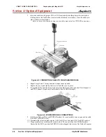
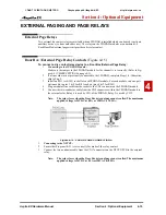
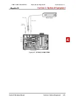
5. Connect the two-conductor cable from the CN5 connectors within the 2PGDAD module to
the external relay. Relay 6 is used by CH1 of the PGDAD, Relay 5 is used by CH2.
Note:
The relay closes when the Door Box/external page zone is called. The maximum
applied voltage is 24VDC at 0.5A or 120VAC at 0.25A .
Figure 4-15: PGDAD PAGE CONNECTIONS
1.
Connecting
to the NTCPU:
2.
Ensure that Program 10-21 is set correctly for mode of the relay contact.
3.
Connect the two-conductor cable from the CN17 connectors on the NTCPU PCB to the external
relay.
Note:
The relay closes when the Door Box/external page zone is called. The maximum
applied voltage is 24VDC at 0.5A or120VAC at 0.25A
CÔNG TY VIỄN THÔNG VIỆT PRO
Chuyên phân phối tổng đài NEC
http://vietpro.com.vn

