Section 2: PCB Installation and Startup
2-46
Section 2: PCB Installation and Startup
Aspila EX Hardware Man-
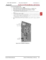
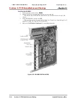
Installing the VoIP PCB:
1. Set the run/block switch to block,
DOWN
.
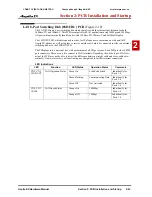
If the VOIPDB is to be used, install this prior to inserting the 16VOIPU PCB into the cab-
inet. Refer to
VoIP (VOIPDB) Daughter Board (Figure 2-20 - Figure 2-21)
(page 2-47)
for
more details.
2. Install the 16VOIPU PCB into a slot.
Note that the white PCB Pull Tab should always be positioned closest to the top of the
cabinet.
3. Set the run/block switch to run,
UP
.
With normal operation, the status LED will flash fast. If trouble was found during the self
diagnostics routine, the status LED will flash slowly.
4. The 16VOIPU PCB will use the first block of 16 trunk ports available. Confirm the ports used
with Program 10-03.
5. Connect the 16VOIPU PCB to the 8SHUBU PCB or to an external switching hub using an
ethernet cable.
6. Refer to the
VoIP Feature Supplement
for required programming.
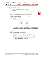
Figure 2-19: 16VOIPU PCB INSTALLATION
The LAN cable that will be connected to the VOIPU PCB must
pass three times (2 turns) through the ferrite sleeve supplied to
comply with EMC requirements.
The ferrite must be located, on the cable, as near as possible to the
plug that will be connected to the PCB.
CÔNG TY VIỄN THÔNG VIỆT PRO
Chuyên phân phối tổng đài NEC
http://vietpro.com.vn

