Chapter 9: Installing the Terminal in an Integrated Configuration 9-17
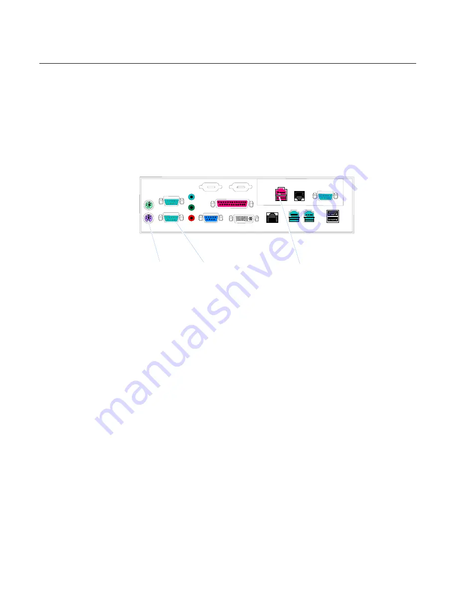
3.
Connect
the
keyboard
cable
to
the
PS/2
connector.
4.
Connect
the
Customer
Display
cable
to
one
of
the
RS
‐
232
connectors.
5.
Connect
the
printer
cable
to
the
24V
USB
connector.
6.
If
you
are
using
the
RS
‐
232
interface
for
the
printer,
connect
the
RS
‐
232
cable
to
one
of
the
RS
‐
232
connectors.
RS232/1
RS232/2
CRT
DVI
Parallel
LAN
Mouse
24V USB
Mic
Line Out
12V USB
Cash Drawer
Kybd
Line In
RS232/4
USB
USB
12V USB
21703
24V USB
RS-232
PS/2
Summary of Contents for RealPOS 70
Page 1: ...NCR RealPOS 70 7402 Release 1 4 User Guide B005 0000 1463 Issue N ...
Page 18: ...xvi ...
Page 96: ...3 34 Chapter 3 Touch Screen Calibration Windows MT 7 12 ...
Page 103: ...Chapter 4 Touch Screen Calibration Windows MT 5 64 SR4 4 7 8 Select Finish 9 Select Calibrate ...
Page 119: ...Chapter 4 Touch Screen Calibration Windows MT 5 64 SR4 4 23 2 Select the Advanced button ...
Page 124: ......
Page 148: ...5 24 Chapter 5 Touch Screen Calibration Windows MT 5 64 SR6 ...
Page 152: ...6 4 Chapter 6 Touch Screen Calibration DOS ...
Page 218: ...9 18 Chapter 9 Installing the Terminal in an Integrated Configuration ...
Page 223: ...Chapter 10 2x20 Customer Display Interface 10 5 CP437 ...
Page 224: ...10 6 Chapter 10 2x20 Customer Display Interface CP858 ...
Page 225: ...Chapter 10 2x20 Customer Display Interface 10 7 CP866 ...
Page 226: ...10 8 Chapter 10 2x20 Customer Display Interface CP932 ...
Page 238: ...11 12 Chapter 11 APA Customer Display Interface 5X7 Character Table ...
Page 239: ...Chapter 11 APA Customer Display Interface 11 13 10x14 Character Table ...
Page 268: ......
Page 280: ...14 6 Chapter 14 Maintenance ...
Page 288: ...16 4 Chapter 16 BIOS Updating Procedures ...
Page 302: ...B 4 Appendix B Feature Kits ...


