Chapter 3: Installation 3-11
8.
If
used,
Connect
the
Sensormatic®
AC
Power
Cord.
9.
If
used,
connect
the
Checkpoint®
interlock
cable.
10.
Turn
on
the
scanner
by
turning
on
the
POS
terminal
or
by
turning
on
the
AC
power
of
the
scanner.
Note:
Some
peripherals
are
limited
to
which
port
they
can
use.
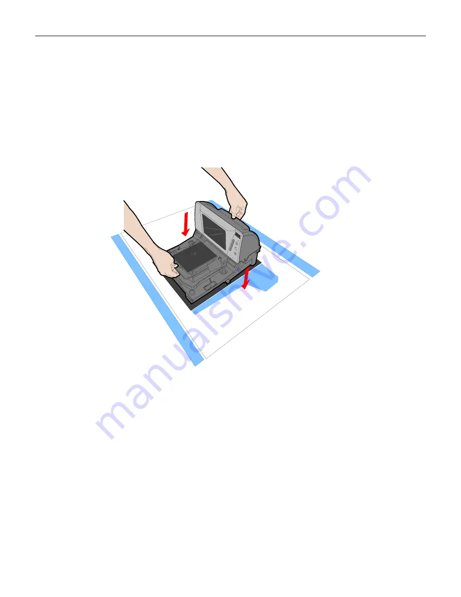
Step 5: RealScan 74 Installation in Checkstand Cutout
25510
To
install
the
RealScan
74
in
the
checkstand
cutout,
perform
the
following
procedure.
1.
Verify
that
the
top
of
the
RealScan
74
supports
are
set
to
the
initial
distance
from
the
top
of
the
checkstand.
Check
dimensions
on
the
“Checkstand
Cutout”
section
in
the
Site
Preparation
chapter.
2.
Holding
the
handles
on
the
back
of
the
tower
cabinet
and
the
front
of
the
unit,
slowly
lower
the
RealScan
74
into
the
checkstand
cutout.
It
should
sit
on
supports
at
the
bottom
of
the
checkstand
cutout.
3.
Install
the
Top
Plate
on
the
four
supports
on
the
scanner.
Note:
It
is
important
that
the
RealScan
74
does
not
rock
on
its
supports.
Make
sure
that
all
adjustable
supports
are
securely
fastened
and
that
the
RealScan
74
is
sitting
on
all
supports.
Note:
Place
the
power
supply
in
a
position
where
spilled
liquids
cannot
fall
onto
it.
Summary of Contents for 74 OFX (7874)
Page 1: ...NCR RealScan 74 OFX 7874 Release 1 1 User Guide 25315 B005 0000 1822 Issue C...
Page 16: ......
Page 42: ......
Page 240: ......
Page 246: ......
Page 248: ...A 2 Appendix A NCR Scanner Programming Tags Reset 11818 Default R0046 Programming Mode R0042...
Page 249: ...Appendix A NCR Scanner Programming Tags A 3 End R0043 Save and Reset R0044 Abort R0045...
Page 253: ...Appendix A NCR Scanner Programming Tags A 7 Hex 2 R0050 Hex 3 R0051 Hex 4 R0052...
Page 254: ...A 8 Appendix A NCR Scanner Programming Tags Hex 5 R0053 Hex 6 R0054 Hex 7 R0055...
Page 255: ...Appendix A NCR Scanner Programming Tags A 9 Hex 8 R0056 Hex 9 R0057 Hex A R0058...
Page 256: ...A 10 Appendix A NCR Scanner Programming Tags Hex B R0059 Hex C R0060 Hex D R0061...
Page 258: ......
Page 264: ......
Page 266: ......


