background image


Service Manual                                                                                                                                            Chapter1. Preface 


©  2016 

Nautilus Hyosung Inc. 

All Rights Reserved.                                   


1-5


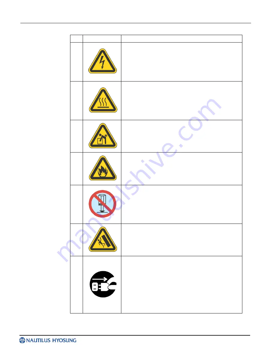
 Description of Precaution Symbols 

Symbol 

Description 


Electrical Shock Warning 

▪ Do not remove cover. Only a maintenance engineer is 

allowed to open the cover. 

▪ Do not touch. You may receive electric shock. 
▪ Make sure to turn off the power when servicing the 

equipment. 


High Temperature Warning 

▪ Do not touch the equipment when it is running. 
▪ The equipment can get extremely hot and may cause a 

burn. 

▪ Make sure to close the cover before running the 

equipment. 


Use Precaution when Moving 

▪ The equipment is heavy. Make sure at least 2 people lift 

or move the equipment. 

▪ Do not attempt to move the equipment alone. You may 

be injured from dropping the heavy equipment. 


Fire Hazard 

▪ Place the equipment in an area away from any   

combustible materials.


▪ The equipment may catch on fire from overheating or   

short circuit of the power supply unit.


Disassembly Warnings 

▪ Do not disassemble or modify the equipment unless you 

are a certified engineer. 

▪ Contact the service center for maintenance, adjustments 

and repairs. 

▪ Improper disassembly may cause fire or electrical shock. 


Collapse Precautions 

▪ Do not place the equipment where the floor cannot 

sustain the weight of the equipment, or on slanted or 
unstable surface. 

▪ Equipment may fall and cause injury or damage. 


Unplug the Equipment 

▪ Stop using the equipment immediately if it smokes, emits 

an unusual smell, makes abnormal sounds, or if liquids 

or other foreign materials enter the equipment. 

▪ If the above-mentioned abnormalities occur, immediately 

turn off the power, unplug the equipment and contact the 
service center. 

▪ If you ignore these symptoms, the equipment may catch 

on fire or cause electric shock. 


Summary of Contents for MONiMAX5300

Page 1: ...Service Manual MONiMAX5300 System V01 00 04 2016 1 25 2016 Nautilus Hyosung Inc All Rights Reserved...

Page 2: ...ion All 2 V1 1 2010 3 Modified chapter 2 3 4 2 3 4 3 V01 00 02 2013 02 04 Changed Manual Format All 4 V01 00 03 2014 06 20 Updated all chapters by Model Name of ATM changed All 5 V01 00 04 2016 01 25...

Page 3: ...Unit Overview 3 1 Operation Panel for Customer OPL 3 2 Encryption PIN Pad 3 7 Panel Control Board 3 9 Bar Code Reader 3 10 Chapter4 Control Electronics Overview 4 1 Disassembly Procedure 4 2 Main Boa...

Page 4: ...1 Unit Block Diagram 8 6 Module and Sensor Replacement 8 7 Adjustment Standard 8 25 Oiling Standard 8 29 Cleaning Standard 8 31 Setting Specifications 8 32 Cable Connection Diagram 8 33 Interface Spec...

Page 5: ...r 1 Preface Contents Purpose 1 1 Audience 1 1 Supported Information 1 1 What is in This Manual 1 1 Conventions 1 2 Abbreviations of ATM 1 2 Safety Precautions English 1 4 Pr cautions pour la s curit F...

Page 6: ...phone numbers provided separately What is in This Manual MONiMAX referred to as MX This manual is designed to provide the maintenance guide for the MX5300 and the detailed description of the following...

Page 7: ...g and maintenance refer to the supervisor operator and technician s tasks performed to keep the ATM operational Screen refers to the text appearing on the customer display Abbreviations of ATM In this...

Page 8: ...Screen Display Board 21 P S Power Supply 22 PIN Personal Identification Number 23 PNC Panel Control Board 24 PTR Printer mainly Receipt Printer 25 S W Switch 26 SIU Sensor and Indications Unit 27 SP...

Page 9: ...operate the equipment Note This equipment has been tested and found to comply with the limits for a Class A digital device pursuant to part 15 of the FCC Rules These limits are designed to provide re...

Page 10: ...the equipment in an area away from any combustible materials The equipment may catch on fire from overheating or short circuit of the power supply unit 5 Disassembly Warnings Do not disassemble or mod...

Page 11: ...n changement ou des modifications dans la construction de ce dispositif qui ne sont pas express ment approuv s par la partie responsable de la conformit pourraient annuler l autorit de l utilisateur d...

Page 12: ...mauvais d montage peut provoquer un incendie ou un choc lectrique Tomber Ne pas placer l quipement dont le sol ne peut pas supporter le poids de l quipement ou sur une surface inclin e ou instable L...

Page 13: ...BATIMENT AVANT D UTILISER Related Documents The related documents are listed as follows If needed please contact staffs of our technical support team and maintenance team Operator Manual Installation...

Page 14: ...g needs This manual is designed to provide maintenance guide for the MX5300 ATM and provide detailed description of the following System configuration Specification of each unit Specifications of expe...

Page 15: ...Up MODEM LAN 10 100Mbps On Board Optional Main Controller CPU P4 2 0GHz Up to 2 8GHz Memory SDRAM 512MB Option 1GB DDR RAM Storage Device HDD 3 5 160GB FDD Option 3 5 1 44MB CD ROM X 52 Operating Syst...

Page 16: ...g Type Thermal Line Printing Printing Width Max 80mm Paper Specification Type Thermal Roll Paper Inside heat sensing Method Width Max 80mm Outer Diameter Max 180 Paper Roll Capacity 3 700 Transaction...

Page 17: ...lus Hyosung Inc All Rights Reserved Chapter2 I Chapter 2 System Configuration Contents About the MX5300 2 1 The Exterior Overview 2 2 Hardware Configuration 2 3 System Block Diagram 2 3 Cable Linking...

Page 18: ...fy accounts and any other inquires through the insertion of a customer s card MX5300 is easy to use easy to service and able to support customer s needs The benefits that the new concept MX5300 provid...

Page 19: ...owing picture shows the front of MX5300 and key units The fascia provides the interface between the customer and MX5300 The customer selects transactions and requests information at the fascia Custome...

Page 20: ...er2 System Configuration 2016 Nautilus Hyosung Inc All Rights Reserved 2 3 Hardware Configuration System Block Diagram System Block Diagram System Block Diagram of MX5300 with optional CE PNC Sidecar...

Page 21: ...r2 System Configuration Service Manual 2 4 2016 Nautilus Hyosung Inc All Rights Reserved Cable Linking Diagram Control Equipment Linking Diagram Control Equipment Linking Diagram of MX5300 with option...

Page 22: ...Service Manual Chapter2 System Configuration 2016 Nautilus Hyosung Inc All Rights Reserved 2 5 Device Interface Linking Diagram Device Interface Linking Diagram of MX5300 with optional CE...

Page 23: ...Chapter2 System Configuration Service Manual 2 6 2016 Nautilus Hyosung Inc All Rights Reserved OPL Linking Diagram OPL Linking Diagram of MX5300 with optional CE...

Page 24: ...Service Manual Chapter2 System Configuration 2016 Nautilus Hyosung Inc All Rights Reserved 2 7 Power Linking Diagram Power Linking Diagram of MX5300 with optional CE...

Page 25: ...Chapter2 System Configuration Service Manual 2 8 2016 Nautilus Hyosung Inc All Rights Reserved Ground Cable Linking Diagram Ground Cable Linking Diagram of MX5300 with optional CE...

Page 26: ...Overview 3 1 Basic Specification 3 1 Operation Panel for Customer OPL 3 2 LCD 3 2 Introduction 3 2 Handling Precautions 3 3 Associated electronic boards 3 4 Encryption PIN Pad 3 7 Common Occurred Prob...

Page 27: ...peakers and associated electronic boards Basic Specification Basic Specification Customer Display Type 15 1 inch TFT LCD Brightness 250cd m 2 Input Method Touch Screen IR Touch Screen NDC DDC style fu...

Page 28: ...ch pixel is divided into RED GREEN BLUE dots which are arranged in vertical stripe and this module can display 16 194 227 colors The TFT LCD panel used for this module is adapted for a low reflection...

Page 29: ...LCD module is operating Put the module display side down on a flat horizontal plane Handle connectors and cables with care 3 Cautions for the operation When the module is operating do not lose CLK ENA...

Page 30: ...Available Touch Panel Bypass Connecting LCD On OFF by detecting Door Sensor 2 Power Unit Input 1 12V GND General LCD when Inverter for 12V used Input 2 24V GND High Brightness LCD when Inverter for 2...

Page 31: ...2016 Nautilus Hyosung Inc All Rights Reserved 3 5 3 ODS Menu Main Menu Mode Change 1 Analog Analog Input 2 Digital Digital Input Bright Change 1 Bright Bright Change 2 Contrast Contrast Change Exit 1...

Page 32: ...ange Position Change 1 Auto Position Auto Position Change 2 Clock Clock Change 3 Phase Phase Change 4 Horizontal Position Horizontal Position Change 5 Vertical Position Vertical Position Change Tool 1...

Page 33: ...tting Description Remarks 1 LED1 Green Power LED Common for USB Serial 2 LED2 Red Flickering at one second intervals during normal operation of EP Common for USB Serial 3 LED3 Red Serial Reception RX...

Page 34: ...th an earth cable which makes it vulnerable to static electricity 4 In case the battery is discharged Troubleshooting Since the problem in this unit involves a security issue you should replace the en...

Page 35: ...Functionality Functionality Control guidance Lights Flickers CARD READER CASH DISPENSER RECEIPT Control the POWER CONTROL signals Power ON OFF AC STOP RECOVER Battery OFF Check SENSOR Signals Door Sen...

Page 36: ...utilus Hyosung Inc All Rights Reserved Bar Code Reader This bar code reader is an automatic identification and optical device It scans the image using CMOS image sensor and transfer the data gathered...

Page 37: ...Reserved Chapter4 I Chapter 4 Control Electronics Contents Overview 4 1 Disassembly Procedure 4 2 Main Board 4 3 Layout Jumper Setting 4 4 Optional Main Board 4 15 Introduction 4 15 Jumper setting 4...

Page 38: ...ification card and etc Basic functions and usage of control electronics used this ATM is almost similar to that of personal computer you have dealt with in your office or your home except a USB Hub us...

Page 39: ...located on the bottom of CE case and remove all cables and connectors to take out the control electronics 3 Remove four screws located on both side in the following figure 4 The following figure is af...

Page 40: ...SLOT xl for ACP 1 5V standard only support AGP 2 0 4X mode 32 bit PCI slot x 5 Integrate VGA Integrated High Performance High Quality 3D Accelerator Support Ultra AGPII with 2GB s bancwidth Built in p...

Page 41: ...4 4 2016 Nautilus Hyosung Inc All Rights Reserved Layout Jumper Setting Layout Jumper Setting Jumpers Jumper Name Description JP4 CMOS RAM Clear 3 pin Block JP1 Keyboard Power On Enable Disabled 3 pin...

Page 42: ...r 3 phone jack Connector 15 pin D Sub Connector COM1 Serial Port COM1 Connector 9 pin Connector COM2 Serial Port COM2 Connector 9 pin Connector PARALLEL Parallel Port Connector 25 pin female Connector...

Page 43: ...omentary switch that connect from the front panel switch to 2 pins power On jumper plow on the motherboard When the power switch on the back of the ATX power supply turned on the full power will not c...

Page 44: ...ed through the BOIS SETUP Please refer to Chapter 3 INTEGRATED PERIPHERALS SETUP section for more detail information 8 Audio Line In Line Out MIC Connector AUDIO_GAME This Connector are 3 phone Jack f...

Page 45: ...umper settings 12 Secondary IDE Connector 40 pin block IDE2 This connector connects to the next set of Master and Slave hard disks Follow the same procedure described for the primary IDE connector You...

Page 46: ...SPEAK This 4 pine connector connects to the case mounted speaker See the figure below 3 IDE Activity LED IDE LED This connector connects to the hard disk activity indicator light on the case 4 Reset...

Page 47: ...ositive while the black should be ground Connect the fan s plug the board taking into consideration the polarity of connectors 8 IR infrared module Headers 5 pine IR only for 845PA 845PAP This connect...

Page 48: ...l a CPU first turn off your system and remove its cover Locate the ZIF socket and open it by first pulling the level sideways away from the socket then upward to a 90 degree angle Insert the CPU with...

Page 49: ...ING Turn off your power when adding or removing expansion cards or other system components Failure to do so may cause severe damage to both your motherboard and expansion cards Procedure For Expansion...

Page 50: ...older for PCI Steering 12 4 PS 2 Compatible Mouse Port 13 N A Numeric Data Processor 14 5 Primary IDE Channel 15 1 Secondary IDE Channel These IRQs are usually available for ISA or PCI devices Interru...

Page 51: ...card has AGP 4X notch show below please make sure your AGP card is AGP 4X 8X 1 5V 0 8V not AGP 2X 3 3V Example 1 SiS 305 ATi Rage 128 Pro AGP card those golden finger is compatible with 2X 4X mode AG...

Page 52: ...y Two DDR 266 SDRAM sockets support up to 2GB IDE interface Support up to two enhanced IDE devices FDD interface Support up to two FDDs Serial ports Two Serial ports 8xRS232 Parallel port One parallel...

Page 53: ...Chapter4 Control Electronics Service Manual 4 16 2016 Nautilus Hyosung Inc All Rights Reserved Block Diagram...

Page 54: ...Service Manual Chapter4 Control Electronics 2016 Nautilus Hyosung Inc All Rights Reserved 4 17...

Page 55: ...al or voltage at JCOM345678 J_COM_V3 J_COM_V4 Set the voltage level of pin34 and pin39 at JCOM345678 Clear CMOS Setup To clear the CMOS Setup for example if you have forgotten the password you should...

Page 56: ...USB_C01 2 USB Port Connectors LAN_USB23 LAN and 2 USB Port Connectors AUDIO_CV1 Audio Vertical Connector PIDE1 SIDE1 Primary and Secondary IDE Connectors FDD1 FDC Connector COM1 COM2 Internal Serial P...

Page 57: ...c All Rights Reserved Keyboard PS 2 Mouse Connector Two 6 pin mini DIN connectors KB MS1 is located on the mounting bracket for easy connection to a keyboard or a PS 2 mouse VGA Connector The product...

Page 58: ...a printer The product includes an on board parallel port accessed through a 25 pin connector RJ45 LAN plus USB Connector The product provide 4 external Universal Serial Bus USB port connectors for US...

Page 59: ...ics Service Manual 4 22 2016 Nautilus Hyosung Inc All Rights Reserved Audio Input and Output Connector The product is equipped with high quality AC97 compatible codec to provide a complete integrated...

Page 60: ...trol Electronics 2016 Nautilus Hyosung Inc All Rights Reserved 4 23 IDE Disk Drive Connector You can attach the IDE Integrated Device Electronics hard disk drives on one channels The connectors suppor...

Page 61: ...Chapter4 Control Electronics Service Manual 4 24 2016 Nautilus Hyosung Inc All Rights Reserved Floppy Disk Drive Connector The product board is equipped with a 34 pin daisy chain drive connector cable...

Page 62: ...Control Electronics 2016 Nautilus Hyosung Inc All Rights Reserved 4 25 Internal Serial Port Connector The product offers eight internal high speeds UART accessed through the 10 pin cable connector or...

Page 63: ...Chapter4 Control Electronics Service Manual 4 26 2016 Nautilus Hyosung Inc All Rights Reserved...

Page 64: ...SB ports for the future new I O bus expansion IrDA Infrared Interface Port The product has a built in IrDA port which supports Serial Infrared SIR or Amplitude Shift Keyed IR ASKIR interface If you wa...

Page 65: ...can supply 12V 500mA to the cooling fan All connectors have the same pin assignments and provide a rotation pin to get rotation signals from fans and notice the system So the system BIOS can recogniz...

Page 66: ...hts Reserved 4 29 PWR RST Buttons and Indicators There are several PWR RST buttons and indicators for monitoring and controlling your CPU board The product provides you with digital input output These...

Page 67: ...Inc All Rights Reserved ATX Power Source Connectors These connectors are for an ATX power supply plugs The power supply plugs are designed to fit these connectors in only one orientation Find the prop...

Page 68: ...Nautilus Hyosung Inc All Rights Reserved 4 31 HDD It is a storage device of CE module within ATM System generic auxiliary storage device to take installation CD to allow for OS and AP program installa...

Page 69: ...2016 Nautilus Hyosung Inc All Rights Reserved ODD It is a storage device of CE module within ATM System generic auxiliary storage device to take installation CD to allow for OS and AP program installa...

Page 70: ...2016 Nautilus Hyosung Inc All Rights Reserved Chapter5 I Chapter 5 Power Supply Contents Overview 5 1 Specification 5 1...

Page 71: ...Test Input Voltage Test Condition WITHSTANDING VOLTAGE PRI SEC 3 0 Kvac 1 5KVac DURING OF TEST 1 min CUTOFF CURRENT 10mA PRI F G 1 5 Kvac INSULATION RESISTANCE PRI SEC 500 Vdc DURING OF TEST 1 min IN...

Page 72: ...12 6 22 8 25 2 Vdc CURRENT 0 2 3 11 12Ap p 0 0 2 0 4 0 17Ap p A METHOD SWITCHING SW REG SWITCHI NG MODE RIPPLE 120 120 500 mVp p NOISE 0 4 0 4 1 0 Vp p SHOOT 4 4 5 O V P 13 4 15 6 26 5 34 Vdc O C P S...

Page 73: ...day 4 Stand by D C output go on while A C input don t turned off neglect P ON N signal Requirement 1 Use the lamp of power supply as below YELLOW LED A C INPUT turn on if A C input is normal GREEN LE...

Page 74: ...ED 8 5V 18AWG UL1007 RED 9 24V 18AWG UL1007 WHITE 10 5V 18AWG UL1007 ORANGE 11 P ON N 18AWG UL1007 GREEN 12 5VSBV 18AWG UL1007 PURPLE 13 S G 18AWG UL1007 BLACK 14 S G 18AWG UL1007 BLACK 15 S G 18AWG U...

Page 75: ...LOW 4 24V 18AWG UL1007 WHITE 5 P ON N 18AWG UL1007 GREEN 6 5V 18AWG UL1007 RED 6 MCU Division PIN No Configuration Size Color Remark CN10 1 S G 18AWG UL1007 BLACK MOLEX 5569 06P 2 S G 18AWG UL1007 BLA...

Page 76: ...7 BLACK 12 PWR I F PIN NO PIN Name Active INACTIVE Description IN OUT 1 P OFF P 5V 0V Application software turn P S off IN 2 S G 3 P ON N 0V OPEN Stand by switch used to turn P S on IN 4 S G 5 BATT OF...

Page 77: ...2016 Nautilus Hyosung Inc All Rights Reserved Chapter6 I Chapter 6 Safe Unit Contents Dial Lock 6 1 How to open the dial lock 6 1 Optional Lock 1 Electronic Lock 6 4 Optional Lock 2 Cencon Lock 6 6...

Page 78: ...ber where you were supposed to stop you cannot reverse the dial to correct The opening procedure must be repeated from the beginning To open a safe with a previously set three number combination i e 1...

Page 79: ...hole If the Change Key does not go in easily the wheels are not aligned for changing Redial the existing combination on the CHANGING Index 3 Turn the Change Key to the RIGHT until it stops approximat...

Page 80: ...your safe always turn the safe handle if present to its fully locked bolts extended position before turning the dial to extend the lock bolt If you notice any resistance DO NOT force the dial to turn...

Page 81: ...the door open 1 Enter 0 0 0 0 0 0 six 6 zeros into the Electronic Lock keypad 2 Enter in the old combination once 3 Enter in the new combination twice Combinations must be six digits in length 4 If a...

Page 82: ...attery 3 Remove the connector by unsnapping it from the two terminals on the top of the battery 4 Replace with NEW 9 Volt alkaline battery CAUTION Hold onto battery terminal connector to avoid pulling...

Page 83: ...Mode combination is used to open the lock without any Smart Key The default Factory Combination is set to 50 25 50 Practice opening the lock in shelved mode with the default factory combination until...

Page 84: ...urity door 6 Turn the dial a minimum of one complete rotation to the left CCW to extent the bolt Note After opening and closing any lock you should always check to ensure that the lock is physically r...

Page 85: ...ation of 50 25 50 This is an option that is only available while the lock is in Shelved Mode and is intended only for temporary use after the ATM is deployed but before the lock is activated It is not...

Page 86: ...6 Extend Bolt Turn the Dial to the left CCW to extend the bolt 7 Power Lock Turn the dial to the left CCW until the Change Key symbol along with Enter Combination is displayed 8 Press 8 EcF Press the...

Page 87: ...de Combination OPr Enter the new shelved mode combination by pressing those digits on the lock s keypad The numbers will be displayed on the LCD as they are entered When the combination has been corre...

Page 88: ...lectromagnetic Components 7 2 Block Diagram 7 4 Disassembly Assembly Diagrams of Modules and Sensors 7 5 Oiling Criteria 7 12 General Oiling Criteria 7 12 Oiling Criteria 7 12 Oiling Criteria for Each...

Page 89: ...Service Manual Chapter7 SPR Receipt Printer 2016 Nautilus Hyosung Inc All Rights Reserved 7 1 Appearance Functional Diagram Appearance Dimension Appearance Dimensions...

Page 90: ...tilus Hyosung Inc All Rights Reserved Diagram for Sensors and Electromagnetic Components Sensors and electromagnetic components of Receipt Printer are arranged as shown in the following figure Table s...

Page 91: ...ULT OFF MS3 Jam Sensor Detects paper jam SG 405 DEFAULT OFF MS4 TPH Cover Switch TPH Cover Open Switch Internal Switch DEFAULT ON MS5 Cutter Switch Identifies cutter regular position Internal Switch D...

Page 92: ...LM339 SENSOR PRT TPH MOTOR FEED TPH MOTOR 232C DRV MAX232 EEPROM AT93C46 A0 A19 D0 D7 I O Port CUTTER MOTOR 2803 MOTOR SMA4032 SOLENOID FONT ROM 1Mx16 bit S3C44B0X 66MHz OSC 12MHz RESET DS1832 128Kx1...

Page 93: ...ams of Modules and Sensors Disassembling TPH Support Assembly 1 Remove the hex bolt M3 1 place of the base bracket assembly and lift up the upper bracket 2 Pull out the TPH cable and the sensor cable...

Page 94: ...rvice Manual 7 6 2016 Nautilus Hyosung Inc All Rights Reserved Disassembling MS3 Jam Sensor 1 Remove the screw M3 1 place at the bottom of the guide outlet assembly from the removed TPH support assemb...

Page 95: ...rinter 2016 Nautilus Hyosung Inc All Rights Reserved 7 7 Disassembling MM3 Returning Motor 1 Remove the screws M2 2 places at the bottom of the guide outlet assembly from the removed TPH support assem...

Page 96: ...utilus Hyosung Inc All Rights Reserved Disassembling TPH 1 Remove the screws from the TPH support assembly Guide outlet pivot M3 2 places to remove the guide outlet assembly 2 Remove the screws that f...

Page 97: ...nd lift up the upper bracket 2 Pull out the TPH cable and the sensor cable from the main PCBA 3 Remove the screws connected to the frame left right M3 4 places to remove the TPH support assembly 4 Rem...

Page 98: ...nter Service Manual 7 10 2016 Nautilus Hyosung Inc All Rights Reserved Disassembling Bracket Tension Assembly 1 Remove the screws M3 2 places that are connected to the base assembly to remove the asse...

Page 99: ...ed 7 11 Disassembling MS1 Paper Set Detection Sensor 1 Remove the next bolt M3 1 place from the base bracket assembly and lift up the upper bracket 2 Plug out the MS1 cable from the main PCBA 3 Remove...

Page 100: ...1 2mm with the grease gun having the 7mm feeder entry 3 Type of lubricants Oil Korea Shell Tellus 100 Grease Shin Etsu G501 Note 1 6M Once every six months 2 1Y Once a year Oiling Criteria 1 Oiling r...

Page 101: ...moving dust oil or grease or cleaning the part or the assembly parts Be careful that the paper contact side in the paper return path is not wet with oil Oiling Criteria for Each Module Oiling Points a...

Page 102: ...OFF ON Baud rate 38400 bps ON OFF Baud rate 115200 bps OFF OFF Baud rate 166000 bps OFF OFF ON OFF OFF ON ON ON ON OFF ON Black mark is not equipped OFF Black mark is equipped ON OFF ON ON OFF ON ON O...

Page 103: ...Receipt Printer 2016 Nautilus Hyosung Inc All Rights Reserved 7 15 Cable Connection Diagram Receipt Printer Cable Connection Diagram Residual Detection Sensor MS7 Transport Motor I F MM3 END Detectio...

Page 104: ...face Upper Unit Interface 1 Interface Specification Async RS 232C 2 Baud Rate 115200bps 3 CPU Serial I F Port Connect to the upper unit P3 0 RxD P3 1 TxD 4 I F Connector P1 Manufacturer AMP Model Name...

Page 105: ...Receipt Printer I F Connector Specifications No REF Usage Remark 1 CN1 Print Motor Cutter I F Printer Head Module 2 CN2 TPH I F 3 CN3_A Near End Sensor 4 CN3_B Paper dispensing Jam Sensor 5 CN3_C Pape...

Page 106: ...7 Sensor Replacement 8 7 Returning Path Sensor 8 8 Regular Position Sensor 8 18 Remaining Note Sensor 8 19 Module Replacement 8 20 Adjustment Standard 8 25 Gate Adjustment 8 25 Cassette Guide Adjustm...

Page 107: ...8 CDU 2016 Nautilus Hyosung Inc All Rights Reserved 8 1 Appearance Functional Diagram CDU for Business Hour MX5300 The following figures show the three sectional diagrams of the CDU CDU is 775 20mm hi...

Page 108: ...ter8 CDU Service Manual 8 2 2016 Nautilus Hyosung Inc All Rights Reserved CDU for Level 1 MX5300 The following figures show the three sectional diagrams of the CDU CDU is 775 20mm high and 497 00 mm w...

Page 109: ...ce Manual Chapter8 CDU 2016 Nautilus Hyosung Inc All Rights Reserved 8 3 Cassette The following figures show three sectional diagrams of the cassette Cassette is 137 50mm high 217 00mm wide and 342mm...

Page 110: ...Chapter8 CDU Service Manual 8 4 2016 Nautilus Hyosung Inc All Rights Reserved Actuator Diagram Six actuators are used The following figure shows their location...

Page 111: ...ual Chapter8 CDU 2016 Nautilus Hyosung Inc All Rights Reserved 8 5 Sensor Diagram The following figure shows the location of 34 sensors in this system Note A Sensor far from the board B Sensor close t...

Page 112: ...Chapter8 CDU Service Manual 8 6 2016 Nautilus Hyosung Inc All Rights Reserved Unit Block Diagram Unit Block Diagram...

Page 113: ...Replacement Turn the power off and remove the CDU cover as shown in the figure to replace sensors and modules The CDU contains a total of 34 sensors including 24 returning path sensors 1 gate operati...

Page 114: ...es each as shown in the figure below 2 Remove the connector and the cable tie to remove the sensor bracket Be careful not to break the connector pin when removing 3 Remove the sensor bracket 4 From th...

Page 115: ...s each from the sensor bracket 2 Remove the connector and the cable tie to remove the sensor bracket Be careful not to break the connector pin when removing 3 Remove the sensor bracket 4 From the remo...

Page 116: ...le tie to remove the sensor supporter Be careful not to break the connector pin when removing 3 Remove the M3 sensor screw 1 place 4 Remove the M3 sensor fastening screws from the removed sensor brack...

Page 117: ...of the sensor bracket 2 Remove the connector and the cable tie to remove the sensor supporter Be careful not to break the connector pin when removing 3 Remove the sensor bracket 4 Remove the M3 sensor...

Page 118: ...ble tie to remove the sensor supporter Be careful not to break the connector pin when removing 3 Remove the sensor bracket 4 Remove the M3 sensor fastening screws to replace from the removed sensor br...

Page 119: ...the left and right sides 2 Remove the connector and the cable tie to remove the sensor supporter Be careful not to break the connector pin when removing 3 Remove the sensor bracket 4 Remove the M3 se...

Page 120: ...e tie to remove the sensor supporter Be careful not to break the connector pin when removing 3 Remove the sensor bracket 4 Remove the M3 sensor fastening screws to replace from the removed sensor brac...

Page 121: ...cable tie to remove the sensor supporter Be careful not to break the connector pin when removing 3 Remove the sensor bracket 4 Remove the M3 sensor fastening screws from the removed sensor bracket 5...

Page 122: ...sensor bracket Be careful not to break the connector pin when removing 3 Press the part of the sensor gently as shown in the figure below to remove the lock and the sensor 4 To insert the sensor inser...

Page 123: ...emove the sensor bracket Be careful not to break the connector pin when removing 3 Press part of the sensor gently as shown in the figure below to remove the lock and the sensor 4 To insert the sensor...

Page 124: ...Remove the connector and the cable tie to remove the sensor bracket Be careful not to break the connector pin when removing 3 Remove the sensor bracket 4 Remove the MP3 sensor screws 2 places each fr...

Page 125: ...snap lock in the rear of the sensor bracket with your hand and then remove the sensor 4 Remove the connector Be careful not to break the connector pin when removing 5 Replace the sensor 6 Connect the...

Page 126: ...omposed of the main board and the DC converter board as shown in the following figure 2 Remove the connector from the board Be careful not to break the connector pin 3 Remove the board M3 screws 4 pla...

Page 127: ...ed 8 21 Main Motor Assembly 1 Remove the main motor cover as shown in the following figure 2 Remove the power cable from the main motor 3 Unscrew the main motor fixing screws M5 4 places 4 Remove the...

Page 128: ...olenoid Assembly 1 Remove the solenoid power cable 2 Remove the 2 E ring 3 Unscrew the solenoid bracket screws M4 2 places 4 Unscrew the solenoid fixing screws M4 4 places 5 Assemble in the reverse or...

Page 129: ...Reserved 8 23 Clutch Assembly 1 The clutch assembly is composed of three clutches as shown in the figure below 2 Remove the M4 screw 1 pace and E Ring to remove the clutch as shown in the above figure...

Page 130: ...assembly 4 Replace the clutch assembly and assemble in the reverse order 4 1 Note When replacing the clutch assembly adjust the tension pulley so that belt tension is about 100g to the direction and a...

Page 131: ...M4 screw 2 places as much as possible 2 Adjust the solenoid position so that the gate is at least 1 5mm away from the shaft when you pull the gate as shown in the below right figure 3 Adjust the solen...

Page 132: ...ing Table of The Upper Guide Setting Specification as it will be changed No Note height The number of Spacer Bolt Spec The length of Screw Note 1 Greater than 74mm Less than 78mm GUIDE SCR M3 5 BLACK...

Page 133: ...ss than 127mm 127 3 Greater than 127mm Less than 132mm 132 4 Greater than 132mm Less than 137mm 137 5 Greater than 137mm Less than 142mm 142 6 Greater than 142mm Less than 147mm 147 7 Greater than 147...

Page 134: ...All Rights Reserved In case the bill width is greater than 150mm At first put the Side Guide under the Push Spring and then insert the hook parts into the holes of Guide Assembly Position 3 Assemble t...

Page 135: ...the belt with lubricant No Location Lubricants Interval Remark 1 Tension Pulley Mobil 1 Y1 Lubricate the friction part between the shaft and the pulley 2 Gate bush Mobil 1 Y1 Lubricate the friction pa...

Page 136: ...8 CDU Service Manual 8 30 2016 Nautilus Hyosung Inc All Rights Reserved 5 Gear support spring hook AlbaniaGreaseEP1 Initial Oiling 6 Note separate assembly gear teeth surface AlbaniaGreaseEP1 Initial...

Page 137: ...Once a year No Location Int Remark 1 CDU Main Body CS1 A B D T CS15 A B D T CS31 A B D T CS31 A B D T CS4 A B D T CS2D T CS13D T CS3 CS5 CS8 CS7 CS17 CS27 CS43 CS6 CS16 CS26 CS42 Guide entrance M6 Re...

Page 138: ...fer to the cable connection diagram S1 Setting Comments 1 2 12 Short Forced EP Download Test mode 1 2 Short Test mode 1 26 Open AP mode 2 CN7 Default setting 1 26 Open 3 FM B D DIP S W Specifications...

Page 139: ...CN4 9P CN7 10P CN3 6P 1 10 1 39 2 6 1 40 8 5 CN12 5P CN9 6P Seq Connector Name No of Pins Use Remark 1 CN1 40 Sensor Unit 2 CN2 8 Motor Clutch Solenoid 3 CN3 6 Additional Sensor Unit 4 CN4 9 RS 232C...

Page 140: ...Rights Reserved Interface Specifications Line connection method RS232C Data rate 9600BPS Error detection method None Parity Framing Error Overrun Error Bcc Check Character configuration START BIT DAT...

Page 141: ...Service Manual Chapter8 CDU 2016 Nautilus Hyosung Inc All Rights Reserved 8 35 2 Abnormal condition CDUM can respond only when the request from the GP is received...

Page 142: ...9 I Chapter 9 Card Reader Contents Overview 9 1 Troubleshooting 9 2 Troubleshooting Tools and Procedure 9 2 Trouble Verification 9 2 Field Repair Scope Recommendation 9 3 Troubleshooting Procedure 9 3...

Page 143: ...rd into the card reader the cardholder begins their transaction session The card reader has an improved bezel design that allows the customer to retain the card when they are inserting and withdrawing...

Page 144: ...ortant to get detailed transaction flow at the time when the problem occurred This will be very useful in resolving the problem 2 Power LED on Controller Board Check whether the LED on the controller...

Page 145: ...l be replaced and inspected or repaired at the depot level Troubleshooting Procedure Troubleshooting Procedure 1 After arriving on site check the fault and complaints with the branch personnel Study t...

Page 146: ...the pollution of electromagnetic components on the transport path it is important to strictly follow the cleaning cycles and methods 1 Using canned air dust out any accumulated debris inside the card...

Reviews: