


Auxiliary 5 V Power Supply
The programmable power supplies and the CPLD core power supply of 1.8 V are all powered
by an auxiliary 5 V power supply which is powered from the 24 V provided by the SLSC
chassis. This 5 V power supply is also available in the prototyping area. The power supply can
support a maximum of 6 A.
Variable Voltage Power Supplies
The MAX V supports VCCIO of 1.2 V, 1.5 V, 1.8 V, 2.5 V, and 3.3 V in order to use several
I/O standards. The SLSC-12101 has user-configurable power supplies for three of the four
CPLD banks. The voltages are set by placing a jumper in the corresponding header connecting
the pair labeled with the desired voltage. The jumper should be placed on the board before the
module is inserted in the SLSC chassis.
Once a voltage is set for a bank, all the signals on that bank need to use an I/O standard
supported by that voltage. For more information about the supported I/O standards and rules to
interconnect I/O standards with the MAX V CPLD, refer to Altera's
MAX V Device Handbook
.
The voltages of all the banks are also routed to the prototyping area to allow the circuits built
there to use it. The maximum current that can be withdrawn from each bank depends on the
maximum current the source can provide, as well as the estimated current used by the CPLD.
Bank 1 is powered directly from the SLSC chassis and, by SLSC Specification 1.0, the module
shall not withdraw more than 400 mA. Banks 2-4 take their power from 24 V on-board power
supplies and can provide up to 2 A. In addition to the limitations imposed by the current limits
on the different rails on the module, you should also consider the power dissipation limitations
as defined in the
Switch Load and Signal Conditioning Module Design Specifications
.
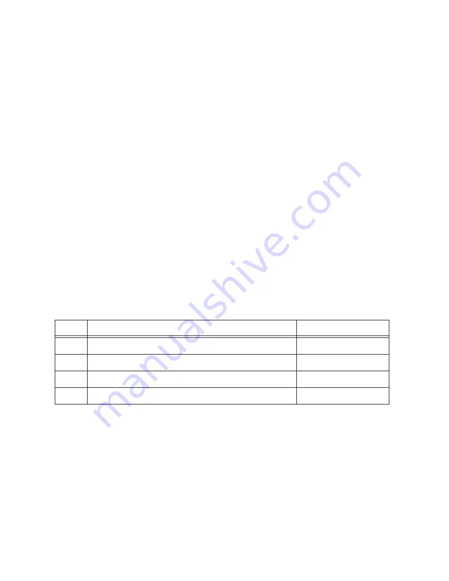
Table 1. Bank Rail Available Voltages and Current Limits
Bank
Available Voltages
Maximum Current
1
3.3 V fixed, provided by the SLSC backplane
400 mA
2
1.2 V, 1.5 V, 1.8 V, 2.5 V, 3.3 V
2 A
3
1.2 V, 1.5 V, 1.8 V, 2.5 V, 3.3 V
2 A
4
1.2 V, 1.5 V, 1.8 V, 2.5 V, 3.3 V
2 A
Module Controller
The SLSC-12101 Module Controller is implemented using Altera's MAX V
5M1270ZF256I5N. The CPLD is shipped pre-programmed with the compiled version of the
Slsc12101Top.vhd
design also included in the SLSC Module Development Kit. The
controller's default image already implements the
EdBlock.vhd
design to handle SLSC
Frames and the required compliance registers as described in Chapter 8 of the
Switch Load
and Signal Conditioning Design Specifications
. Through the ED Mode, the controller can
access the peripherals present on the board, such as the front panel LEDs, the front panel
rotary switch, and 17 8-bit I/O ports routed from the CPLD to the prototyping area.
SLSC-12101 User Guide
|
© National Instruments
|
9