3D TRASAR
5500 - Installation & Operation Manual
521-OM0108.88
Copyright
2009 Nalco Company
2-43
Technical Help
(630) 305-CHEM
2.7.11 Pellet Feeder Connections
(User wired in Controller Box or Junction Box)
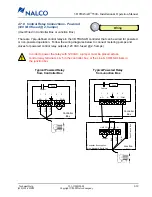
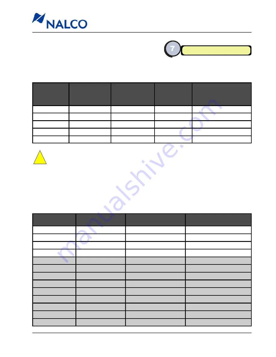
The pellet feeder is wired using the supplied pellet feeder
cable (
P/N 060-TR5311.88
). The cable needs to be hardwired at the controller and connected to
the pellet feeder via the cable connector. The pellet feeder operates on 24 VDC, 0.5 amp, power.
Wiring
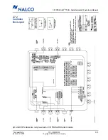
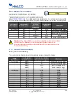
2.7.12 System Probe Connections
(Factory wired in Controller Box)
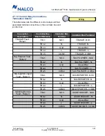
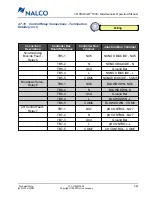
Probe wiring for the Fluorometer and Conductivity probe is done at the factory.
Connection
Description
Controller Box
Board Reference
Controller Box
Terminal
(Removable
Connector)
Junction Box
Terminal
Wire Color
Pellet Feeder
TB11
ISO Gnd
Gnd
Blue with White stripe
TB11
B
B
Orange with White stripe
TB11
A
A
White with Orange stripe
TB11
ISO Gnd
Gnd
Black
TB11
24V
24V
White with Blue stripe
Probe
Description
Controller Box
Board Reference
Controller Box Terminal
(Removable Connector)
Wire Color
Fluorometer
TB15
A
White with Orange stripe
TB15
B
Orange with White stripe
TB15
Gnd
Blue with White stripe
TB15
6V
White with Blue stripe
Conductivity
J7-1
Wht
White
J7-2
Blk
Black
J7-3
Gnd
Shield
J7-4
Red
Red
J7-5
Blk
Black
J7-6
Gnd
Shield
J7-7
Grn
Green
J7-8
Blk
Black
J7-9
Gnd
Shield
!
Important:
Pay close attention to orientation and placement of terminal block
for Pellet Feeder. Miswiring, or improperly placing the terminal on the
controller board could damage both pellet feeder and controller, which is not
coveed under warranty.

