521-OM0108.88
Copyright
2009 Nalco Company
8-2
Technical Help
(630) 305-CHEM
3D TRASAR
5500 - Installation & Operation Manual
8.2
Clean Fluorometer Flow Cell
Shut off both the inlet and outlet shut-off valves. Unscrew cap located on top of the flow switch,
remove flow switch shuttle assembly.
Using the flow cell brush (
P/N 500-P2817.88
) provided with the Start-up kit (
P/N 500-TSRKIT.88 or
500-TSRKITSTR.88
), gently push the brush down through the opening and scrub the full length of
the flowswitch and fluorometer tube.
After cleaning is complete, check fluorometer calibration (Refer to Section 4.10.3).
8.3
Check/replace Fluorometer Desiccant
The fluorometer uses a desiccant canister and a color-coded humidity indicator to ensure that the
optics are not exposed to condensation.
Monthly, check the color of the desiccant indicator on the front of the 3D TRASAR fluorometer.
If the indicator is blue, desiccant does not need to be replaced. If the indicator is pink, unscrew the
desiccant cover from fluorometer. Replace both the indicator (
P/N 060-TR5223.88
) and desiccant
canister (
P/N 060-TR5222.88
).
8.4
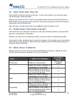
Check Sensor Calibration
Refer to Section 4.10.3 to 4.10.6 for recommended calibration procedures. Calibrate as recom-
mended by the maintenance schedule or if an error is detected.
Sensor
Reason for Calibration
# Calibration
Points
Fluorometer
Monthly, to verify accuracy
2 (blank and
S0940)
pH
Monthly, to fine-tune calibration to
compensate for minor drifting.
1
After installation of new probe, or
if probe readings become erratic
due to fouling/degradation.
2
ORP
Monthly, to fine-tune calibration to
compensate for minor drifting.
1
After installation of new probe, or
if probe readings become erratic
due to fouling/degradation.
2
Conductivity
Monthly, to fine-tune calibration to
compensate for minor drifting.
1
After installation of new probe, or
if probe readings become erratic
due to fouling/degradation.
2

