3D TRASAR
5500 - Installation & Operation Manual
521-OM0108.88
Copyright
2009 Nalco Company
2-49
Technical Help
(630) 305-CHEM
2.8
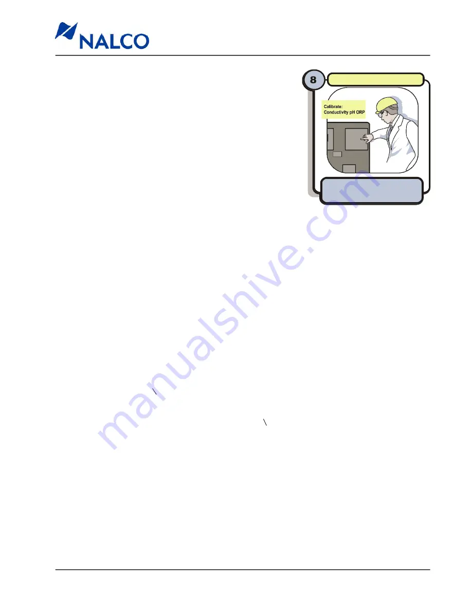
STEP 8 – Calibration & System
Checkout
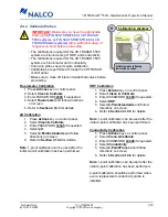
Before starting up the 3D TRASAR system, it is important to
verify probe calibration and test the plumbing and electrical
connections.
2.8.1 Establish Sample Flow & Apply Power
1. Check all unions and probe connections for tightness.
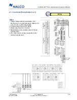
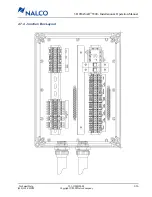
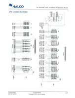
2. Double check all cables to ensure correct and tight electrical
connections.
3. Slowly open the inlet and outlet ball valves on the 3D
TRASAR system and Pellet Feeder (if installed).
4. Check for leaks and tighten where necessary.
5. Verify that a minimum of 5 gpm is flowing through the unit as indicated by the rotometer
.
6. Verify that the circuit breaker in the appropriate electrical service box is switched on.
7. Flip the 3D TRASAR controller power switch to “ON”.
8. Flip the Pellet Feeder power switch to “ON” (if installed).
9. Adjust the water flow through the fluorometer to a minimum of 0.5 gpm as indicated by the
flowswitch.
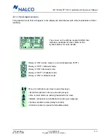
10. Verify that a “No Flow Alarm” does not exist on the 3D TRASAR controller display. No flow is
indicated by a flashing “F”.
11. Verify that a “System Interlock” alarm does not exist on the 3D TRASAR controller display
.
System Interlock alarms are indicated by a flashing “I”.
Calibration & checkout
Calibrate probes following
instruction on screen.

