Installation
FP0
6 - 4
Matsushita Automation Controls
6.1 Adding Expansion Units
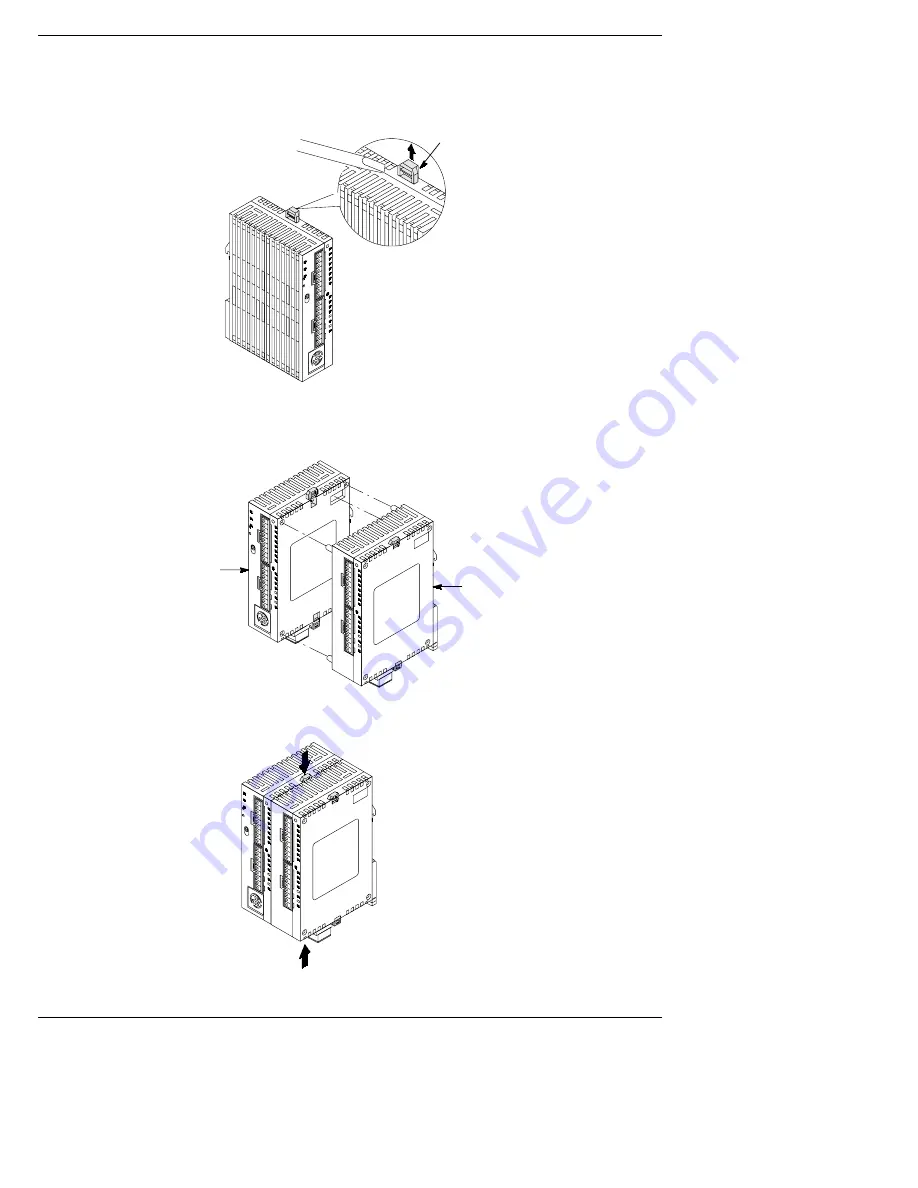
2.
Raise the expansion hooks on the top and bottom sides of
the unit with a screwdriver.
Expansion hook
3.
Align the pins and holes in the four corners of the control unit
and expansion unit, and insert the pins into the holes so that
there is no gap between the units.
Control unit
Expansion unit
4.
Press down the expansion hooks raised in step 2 to secure
the unit.
Summary of Contents for FP0 Series
Page 1: ...PROGRAMMABLE CONTROLLER FP0 Hardware is a global brand name of Matsushita Electric Works...
Page 12: ...Overview FP0 1 2 Matsushita Automation Controls...
Page 20: ...Overview FP0 1 10 Matsushita Automation Controls 1 4 Programming Tools...
Page 76: ...Analog I O Unit FP0 4 2 Matsushita Automation Controls...
Page 94: ...Analog I O Unit FP0 4 20 Matsushita Automation Controls 4 7 Averaging Function...
Page 96: ...I O Allocation FP0 5 2 Matsushita Automation Controls...
Page 102: ...Installation FP0 6 2 Matsushita Automation Controls...
Page 114: ...Wiring FP0 7 2 Matsushita Automation Controls...
Page 134: ...Wiring FP0 7 22 Matsushita Automation Controls 7 9 Wiring the RS232C Port...
Page 136: ...Connecting the I O P Display Panel FP0 8 2 Matsushita Automation Controls...
Page 141: ...Chapter 9 Trial Operation 9 1 Before Turning ON the Power 9 3 9 2 Turning the Power ON 9 4...
Page 142: ...Trial Operation FP0 9 2 Matsushita Automation Controls...
Page 146: ...Self Diagnostic and Troubleshooting FP0 10 2 Matsushita Automation Controls...
Page 160: ...Self Diagnostic and Troubleshooting FP0 10 16 Matsushita Automation Controls 10 3 Error Codes...
Page 162: ...Dimensions FP0 A 2 Matsushita Automation Controls...
Page 172: ...Record of changes FP0 R 2 Matsushita Automation Controls...


