v.090220
7
ENGLISH
ASSEMBLY INSTRUCTIONS
NOTE: If the connector is not properly assembled, the shift rod will pivot and you
will not be able to change speeds or change directions.
ATTACH CHUTE DIRECTIONAL CONTROL
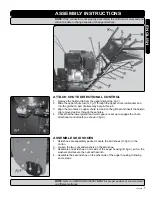
1. Remove the hairpin clip from the upper gimbal (
pp, fig.7
).
2. Slide the upper chute rod (
m, fig.7
) through the upper chute rod bracket and
into the gimbal. A pair of pliers may help in this job.
3. Align the two holes on upper chute rod and on the gimbal and insert the hairpin
clip removed earlier, through these holes.
4. Check that the lower gimbal and worm gear are set up to engage the chute
directional control teeth (
as shown in fig.8
).
ASSEMBLE SKID SHOES
1. Skid shoes are separately packed. Locate the skid shoes (
U, fig.9
) in the
carton.
2. Loosen the two nuts and washers on the skid shoe.
3. Assemble one skid shoe on one side of the auger housing (
B, fig.9
), put on the
washers and secure the nuts with wrench.
4. Assemble the second shoe on the other side of the auger housing, following
same steps.
NOTE: Refer to SKID SHOE ADJUSTMENT for proper position of snow removal
on different surfaces.
Summary of Contents for WSG112
Page 22: ...22 WSG112 ENGLISH FRANÇAIS ...
Page 23: ...v 090220 23 FRANÇAIS ENGLISH SCHEMATIC DRAWING SCHÉMA ...
Page 24: ...24 WSG112 ENGLISH FRANÇAIS SCHEMATIC DRAWING SCHÉMA ...
Page 25: ...v 090220 25 FRANÇAIS ENGLISH SCHEMATIC DRAWING SCHÉMA ...
Page 59: ...12 WSG112e ENGLISH ...
Page 61: ...14 WSG112e ENGLISH FRANÇAIS SCHEMATIC DRAWING SCHÉMA ...
Page 62: ...v 090220 15 FRANÇAIS ENGLISH SCHEMATIC DRAWING SCHÉMA ...


