3-60 Administrator’s Handbook
66. IKE: phase 1 auth failure sg [IP Address] profile [Name], sg [IP Address] code [code]
67. IKE: phase 1 resend timeout sg [IP Address] profile [Name], sg [IP Address]
68. IKE: phase 1 complete sg [IP Address] profile [Name], sg [IP Address]
69. IKE: phase 2 hash failure sg [IP Address] profile [Name] sg [IP Address]
70. IKE: no matching ph2 proposal sg [IP Address] profile [Name] sg [IP Address]
71. IKE: ph2 resend timeout sg [IP Address] profile [Name], sg [IP Address]
72. IKE: phase 2 complete sg [IP Address] profile [Name], sg [IP Address]
73. IPSEC: Dead Peer Detected sg [IP Address] profile [Name], sg [IP Address]
74. L2TP: tunnel up, rem: [IP Address], via: [IP Address] id: [ID]
75. L2TP: tunnel down, rem: [IP Address], tunnel id: [ID]
76. L2TP: peer failed to authenticate, tunnel id: [ID]
77. L2TP: no matching profile for rcvd hostname, id: [ID]
78. L2TP: session up, session id: [SessionID], tunnel id: [ID]
79. L2TP: session down, session id: [SessionID]
80. L2TP: tunnel result code = [Result], error code = [Error]
81. L2TP: session result code = [Result], error code = [Error]
82. SCHED: Next retr y in [Num.] seconds profile [Name]
Procedure for Default Installation for ICSA firewall certification of Small/Medium
Business Category Module (ADSL Routers)
Note:
The following installation procedure outlines steps needed to enable required features to comply with
ICSA firewall cer tification. For more information please go to the following URLs:
http://www.icsalabs.com/icsa/docs/html/communities/firewalls/pdf/4.1/baseline.pdf
http://www.icsalabs.com/icsa/docs/html/communities/firewalls/pdf/4.1/smb.pdf
Install via the Console menu
1.
Access the Router through the serial inter face (if available) or telnet to the product from the private (LAN)
side. DHCP ser ver is enabled on LAN by default. See
“Connecting through a Telnet Session” on page 1-4
.
Set up a Connection Profile to configure WAN connectivity: (Follow the Easy Setup instructions in the
Quickstar t Guide, or create a new Connection Profile. See
“Creating a New Connection Profile” on
page 2-8
.)
2.
Go to
Easy Setup
…
3.
Set
Data Circuit VPI
(0-255) to the desired value
4.
Set
Data Circuit VCI
(32-65535) to the desired value
5.
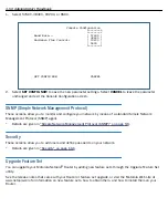
Select
NEXT SCREEN
Summary of Contents for Netopia Embedded Software
Page 10: ...x Administrator s Handbook ...
Page 16: ...1 6 Administrator s Handbook ...
Page 44: ...2 28 Administrator s Handbook ...
Page 108: ...3 64 Administrator s Handbook ...
Page 176: ...5 34 Administrator s Handbook ...
Page 202: ...6 26 Administrator s Handbook ...
Page 244: ...7 42 Administrator s Handbook ...
Page 340: ...Index 6 ...


